Server cabinet

A technology for server cabinets and evaporator fans, which can be used in cabinets/cabinets/drawer components, electrical equipment casings/cabinets/drawers, cooling/ventilation/heating renovations, etc., and can solve air-conditioning indoor units and air-conditioning outdoor units Complicated connections, restrictions on the use of rack-mounted servers, increased operation and maintenance costs, etc., to reduce energy consumption, prevent excessive or low temperature, and save engineering costs

Pending Publication Date: 2017-08-18
铨高科技(珠海)股份有限公司
View PDF13 Cites 5 Cited by
  • Summary
  • Abstract
  • Description
  • Claims
  • Application Information

AI Technical Summary

Problems solved by technology

[0004] However, the disadvantage of the server cabinets of existing rack-mounted servers is that when a large number of servers are installed on the server cabinets, it is easy to cause the internal temperature of the server cabinets to remain high for a long time. Build a cooling system to cool server racks
However, when building a refrigeration system, it is necessary to perform cumbersome operations such as wiring and buried pipes in the computer room, and it is necessary to design the hot and cold aisles of the server cabinets.
In addition, it is necessary to design the installation positions of the air-conditioning indoor unit and the air-conditioning outdoor unit of the refrigeration system, and to make complex connections between the air-conditioning indoor unit and the air-conditioning outdoor unit, which increases the project cost
Moreover, if the design of the refrigeration system is not standardized, there are likely to be hidden dangers in quality and safety, which will increase the cost of operation and maintenance. Especially for some small computer rooms, the construction of a refrigeration system often requires huge construction costs, making the cabinet server There are major restrictions on the use of

Method used


Image

  • Server cabinet
  • Server cabinet
  • Server cabinet

Examples


Embodiment Construction

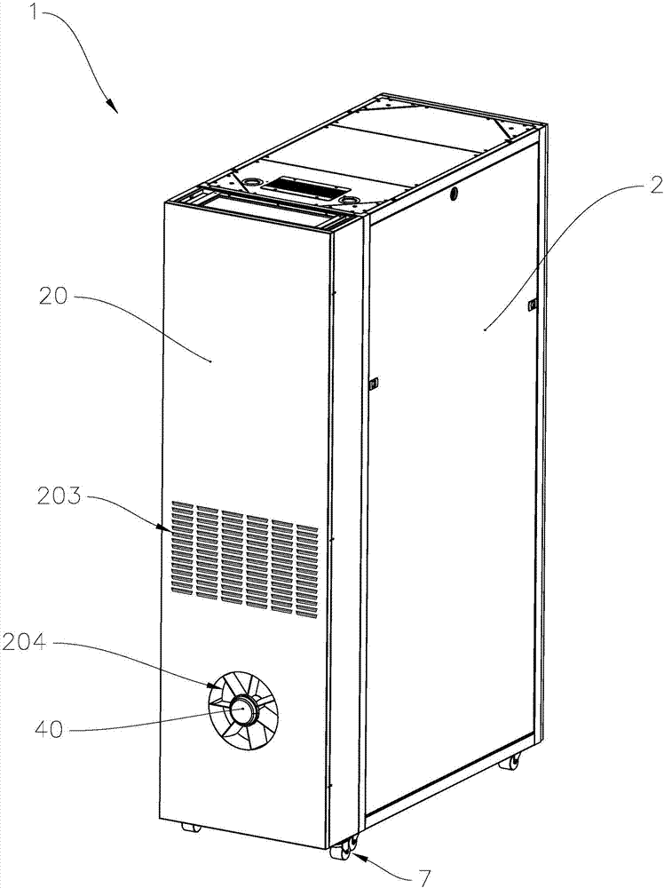
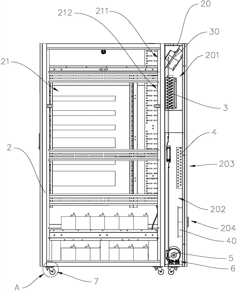
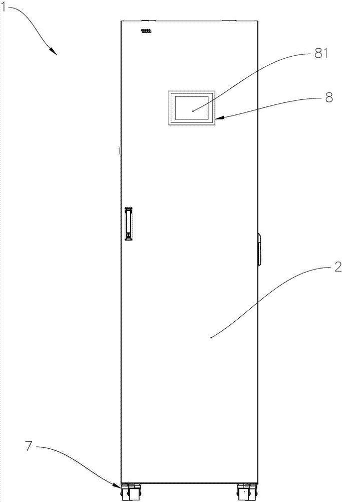
[0031] refer to Figure 1 to Figure 3 , the server cabinet 1 includes a cabinet body 2, a cabinet door 20, an evaporator 3, an evaporator fan 30, a condenser 4, a condenser fan 40, a compressor 5, an expansion valve, a shock absorber 6, a shock absorber wheel set 7, and a control Module 8 and sealing material 9 . Wherein, the evaporator 3, the evaporator fan 30, the condenser 4, the condenser fan 40, the compressor 5 and the expansion valve form a refrigeration system.

[0032] The cabinet body 2 is provided with a first cavity 21, and the first cavity 21 is used for installing various types of servers, such as cloud servers, firewall servers, and the like. Moreover, the first cavity 21 is provided with an air return port 211 and an air outlet port 212 .

[0033] refer to Figure 4 and Figure 5 , and combined with figure 2 , the refrigeration system is arranged on the cabinet door 20, the cabinet door 20 is hinged on the cabinet body 2 through hinges, the cabinet door 2...


PUM


Abstract

The invention provides a server cabinet, which comprises a cabinet body, a cabinet door, an evaporator, an evaporator fan, a condenser, a condenser fan, a compressor, an expansion valve and a shock absorbing device, and is characterized in that the cabinet body is provided with a first cavity, the first cavity is provided with a return air inlet and an air outlet, the cabinet door is hinged on the cabinet body, the cabinet door is provided with a second cavity and a third cavity, the evaporator is installed in the second cavity, the evaporator is located at the air outlet, the evaporator fan is installed in the second cavity, the evaporator fan is located at the return air inlet, the condenser is fixedly installed in the third cavity, the condenser fan is fixedly installed in the third cavity, the compressor is installed in the third cavity, a suction end of the compressor is connected with the evaporator, a discharge end of the compressor is connected with the condenser, the expansion valve is connected between the evaporator and the condenser, and the shock absorbing device is connected between the compressor and the cabinet door. The server cabinet has the advantages of good heat exchange effect, low energy consumption, low vibration and possession of an independent refrigerating system.

Description

technical field [0001] The invention relates to a server cabinet, in particular to a server cabinet with a cooling system. Background technique [0002] With the rapid development of information technology, whether it is an enterprise or an individual, the use of personal computers is becoming more and more extensive, and computers have become an indispensable part of daily business. However, with the gradual maturity of communication technology, ordinary personal computers can no longer meet the business needs of enterprises. Therefore, servers such as cloud servers and firewall servers have been developed successively to meet the daily business needs of various enterprises. [0003] Among them, taking a rack-mounted server as an example, this type of server is to install a large number and various types of servers in a server rack, so that the rack-mounted server has the advantages of saving space and being easy to manage, and can also make multiple Servers can work toget...

Claims


Application Information

Patent Timeline
Patent Type & Authority Applications(China)
IPC IPC(8): H05K7/20H05K5/02
CPCH05K5/0217H05K7/20836
Inventor 郭冷昕廖志辉
Owner 铨高科技(珠海)股份有限公司
Why Eureka
Try Eureka