Mixing apparatus and its use

一种混合装置、脊部的技术,应用在混合装置的应用领域,能够解决结构昂贵等问题

Active Publication Date: 2017-08-18
METSO OUTOTEC (FINLAND) OY
View PDF4 Cites 5 Cited by
  • Summary
  • Abstract
  • Description
  • Claims
  • Application Information

AI Technical Summary

Problems solved by technology

Currently, mixing devices used in demanding applications in hydrometallurgy typically have concave bottoms, which function more efficiently than flat bottoms, but are rather expensive structures to build

Method used


Image

  • Mixing apparatus and its use
  • Mixing apparatus and its use
  • Mixing apparatus and its use

Examples


Embodiment Construction

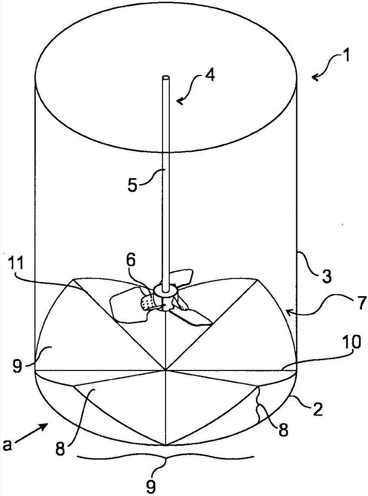
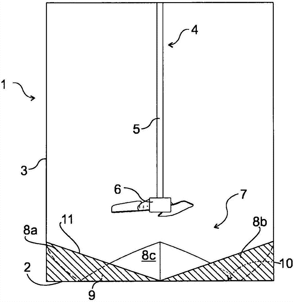
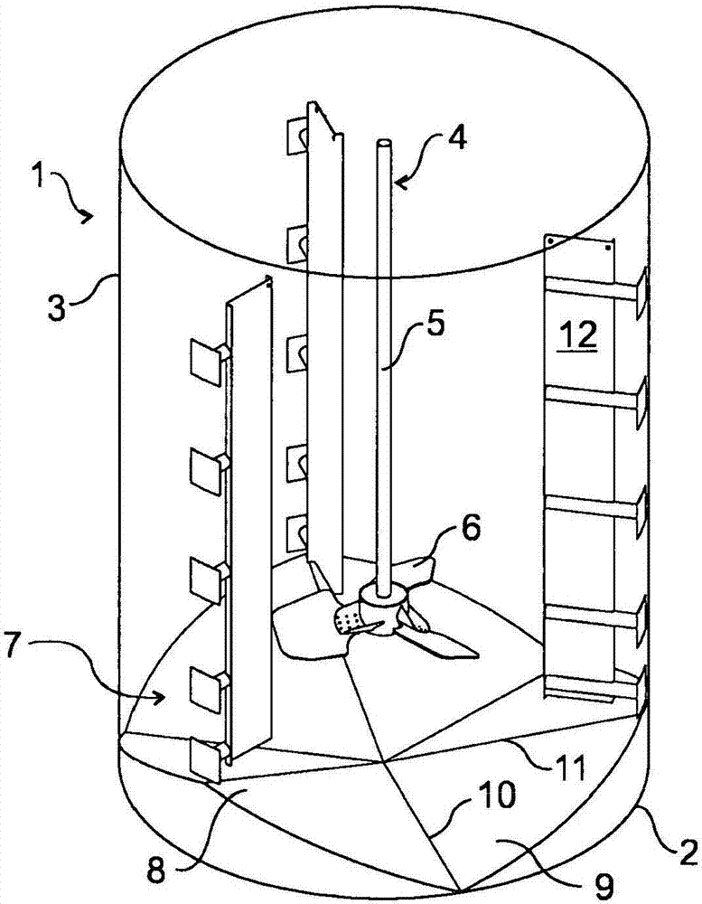
[0051] Figure 1A An exemplary embodiment of a mixing device according to the invention is shown in a side view. exist Figure 1A As well as in the remaining drawings, structural details have been omitted for clarity. The mixing device according to the invention comprises a tank 1 with a bottom 2 and walls 3 . The bottom 2 is circular and the groove 1 is a straight cylinder. The mixing device also comprises stirring means 4 with a rotating shaft 5 and an impeller 6 . exist Figure 1A Among them, the impeller 6 is a downward pumping hydrofoil impeller. The dimensions of the tank 1 and stirring means 4 may vary depending on the particular application in which the mixing device is used. At the bottom 2 of the tank 1 there is a corrugated structure 7 . The corrugated structure 7 has four ridges 8 and corresponding recesses 9 arranged such that the angle between two adjacent ridges 8 and corresponding recesses 9 is equal to all ridges 8 and corresponding recesses 9 is the same...


PUM


Abstract

A mixing apparatus for mixing particles in a liquid and its use are disclosed. The mixing apparatus comprises a tank (1) having a bottom (2) and a substantially vertical side wall (3), an agitation means (4) comprising a rotation shaft (5) located vertically and centrally in the tank (1), and an impeller (6) arranged at a height above the bottom (2) at the end of the rotation shaft (5) and the impeller (6) being a downward pumping axial or mixed flow impeller. The bottom (2) is equipped with a corrugated formation (7) comprising alternate consecutive ridges (8) and valleys (9), the ridges (8) and valleys (9) extending radially in relation to a center of the bottom (2), whereby the valleys (9) concentrate and channel the mixing power near to the bottom (2) to direct the flow of the liquid and to increase the velocity of the flow near to the bottom (2).

Description

technical field [0001] The invention relates to a mixing device for mixing particles in a liquid. The invention also relates to the use of mixing devices. Background technique [0002] The use of mixing devices to suspend solid particles in a liquid is a common process step in many industrial trades. Typically, the mixing device comprises a trough, which is a cylinder with a flat bottom or a concave bottom. The mixing device also includes an agitator having a shaft extending downwardly from the top of the tank and an impeller mounted on the end of the shaft near the bottom of the tank. The impeller is usually positioned in the center of the trough above the bottom, and the rotation of the impeller creates movement in the liquid being mixed. Depending on the application, axial or radial pumping impellers or mixed flow impellers can be used. The mixing tank also contains baffles, which are designed to direct the flow of liquid in the desired direction and reduce turbulence...

Claims


Application Information

Patent Timeline
Patent Type & Authority Applications(China)
IPC IPC(8): B01F7/22B01F15/00B01F27/91
CPCB01F27/91B01F35/531B01F35/5312C22B3/02C22B11/08B01F2101/45Y02P10/20B01F23/50B01F27/86B01F29/401
Inventor M·拉特瓦-科科
Owner METSO OUTOTEC (FINLAND) OY
Why Eureka
Try Eureka