
Portable terminal cradle

A technology of portable terminals and support frames, which is applied in the direction of machine tables/stands, support machines, telephone structures, etc., can solve the problems of limited use, complexity, and inconvenient use, and achieve the effect of preventing internal clutter and improving the convenience of use

Inactive Publication Date: 2017-08-18
尹良俊
View PDF6 Cites 5 Cited by
  • Summary
  • Abstract
  • Description
  • Claims
  • Application Information

AI Technical Summary

Problems solved by technology

[0004] However, the conventional portable terminal brackets can only fix the portable terminal in a specified direction and a specified angle, which is limited in use. The combination and separation of the portable terminal is complex and complicated, and there are problems such as inconvenience in use
[0005] On the one hand, Korean Authorized Utility Model No. 20-0470827 discloses a magnet holder for a portable terminal that uses magnetic force to disassemble a portable terminal. The structure in which a magnet is attached to the surface of an iron ball has the advantage of being able to change the angle. Due to the weight of the portable terminal, it is possible to change the storage angle arbitrarily, especially when it is stored in a vehicle, the storage angle cannot be stably maintained due to inconvenience caused by arbitrarily changing the storage angle due to the vibration of the vehicle or the rotation of the vehicle.

Method used


Image

  • Portable terminal cradle
  • Portable terminal cradle
  • Portable terminal cradle

Examples


Embodiment Construction

[0022] Hereinafter, preferred embodiments of the portable terminal stand according to the present invention will be described in detail with reference to the attached drawings.

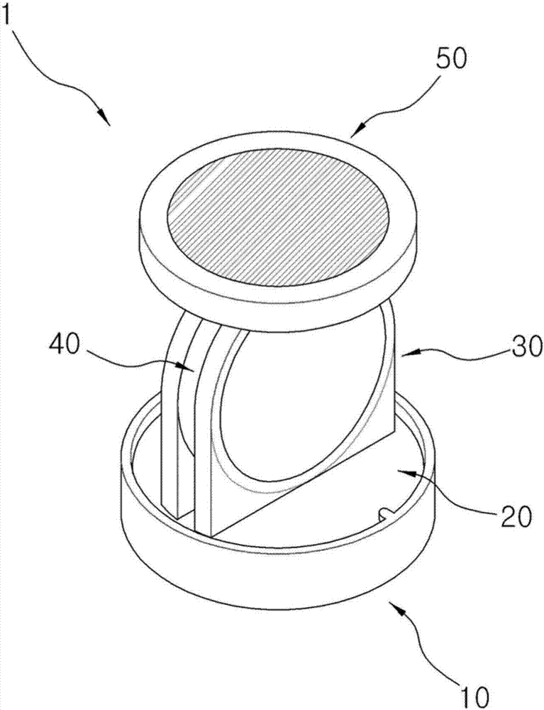
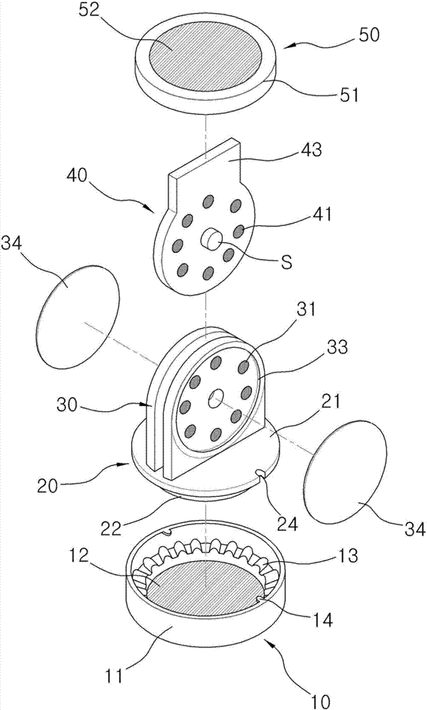
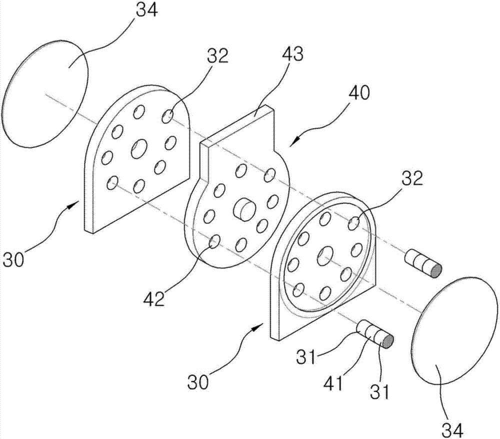
[0023] Figure 1 to Figure 5 It is a drawing illustrating the portable terminal stand of the present invention. The portable terminal stand 1 of the present invention includes a base part 10 , a horizontal rotation part 20 , a vertical support frame 30 , a vertical rotation part 40 and a shelf part 50 .

[0024] The above-mentioned base member 10 is an installation surface on which the bracket 1 of the present invention is to be installed, that is, a part that is attached and fixed to a dashboard of a vehicle, a table or a dining table, and includes a base body 11 and a base plate 12 .

[0025] The above-mentioned base body 11 can be in the shape of a cylinder with an open upper surface and a hollow interior, and an adhesive unit for attachment and fixing can be provided on the installation surface of...


PUM


Abstract

The present invention relates to a portable terminal cradle comprising: a base member fixed to an installation surface; a horizontally rotating member, which is coupled to the base member to be able to rotate in the horizontal direction with regard to the installation surface, and which has a vertical support table formed to protrude from the upper surface thereof; a vertically rotating member coupled to the vertical support table to be able to rotate in the vertical direction with regard to the installation surface; and a cradling member formed on one end of the vertically rotating member such that a portable terminal is attached to / detached from the same. The present invention is advantageous in that the cradling angle of a portable terminal can be adjusted freely, and the portable terminal can remain cradled stably at the adjusted angle, in a convenient manner.

Description

technical field [0001] The invention relates to a portable terminal bracket, which can stably place the portable terminal in various directions and angles. Background technique [0002] The use of portable terminals such as smart phones and tablet PCs is rapidly increasing, and their functions include not only voice calls but also reception of broadcasting and viewing videos, etc., and are embodied in the form of multimedia devices with composite functions. [0003] These portable terminals can be used not only on the go, but also on a dashboard inside a vehicle, on a table in an office or at home, and various forms of portable terminal holders are produced. [0004] However, the conventional portable terminal brackets can only fix the portable terminal in a specified direction and a specified angle, which is limited in use. The combination and separation structure of the portable terminal is complex and complicated, and there are problems such as inconvenient use. [0005]...

Claims


Application Information

Patent Timeline
Patent Type & Authority Applications(China)
IPC IPC(8): B60R11/02
CPCB60R11/02B60R11/0235B60R2011/0057B60R2011/007B60R2011/0087B60R2011/0071F16M11/041F16M11/10F16M11/2014F16M13/00F16M13/02F16M2200/024H04M1/04F16B2200/83B60R11/0241B60R11/0252F16B1/00G09F23/00
Inventor 尹良俊
Owner 尹良俊
Learn More