Valve device for fuel injection valve

A technology of fuel injection valve and valve device, which is applied in the direction of fuel injection device, charging system, machine/engine, etc., can solve the problems of atomization of fuel spray, and achieve the reduction of fuel velocity, small pressure loss, and promotion of atomization. Effect

Active Publication Date: 2017-08-18
MITSUBISHI ELECTRIC CORP
View PDF7 Cites 4 Cited by
  • Summary
  • Abstract
  • Description
  • Claims
  • Application Information

AI Technical Summary

Problems solved by technology

For example, in the valve device mentioned in Patent Document 1, due to the main flow from the center of the valve seat toward the center of the inlet of the nozzle hole provided in the nozzle hole plate, and the return flow that flows temporarily to the outer peripheral side of the nozzle hole plate, it flows into the nozzle hole. Collision between the fuel spray atomization

Method used


Image

  • Valve device for fuel injection valve
  • Valve device for fuel injection valve
  • Valve device for fuel injection valve

Examples


Embodiment approach 1

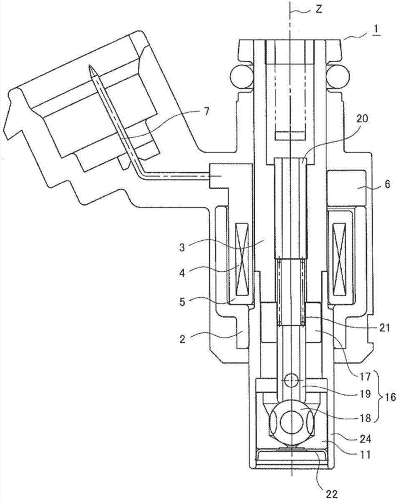
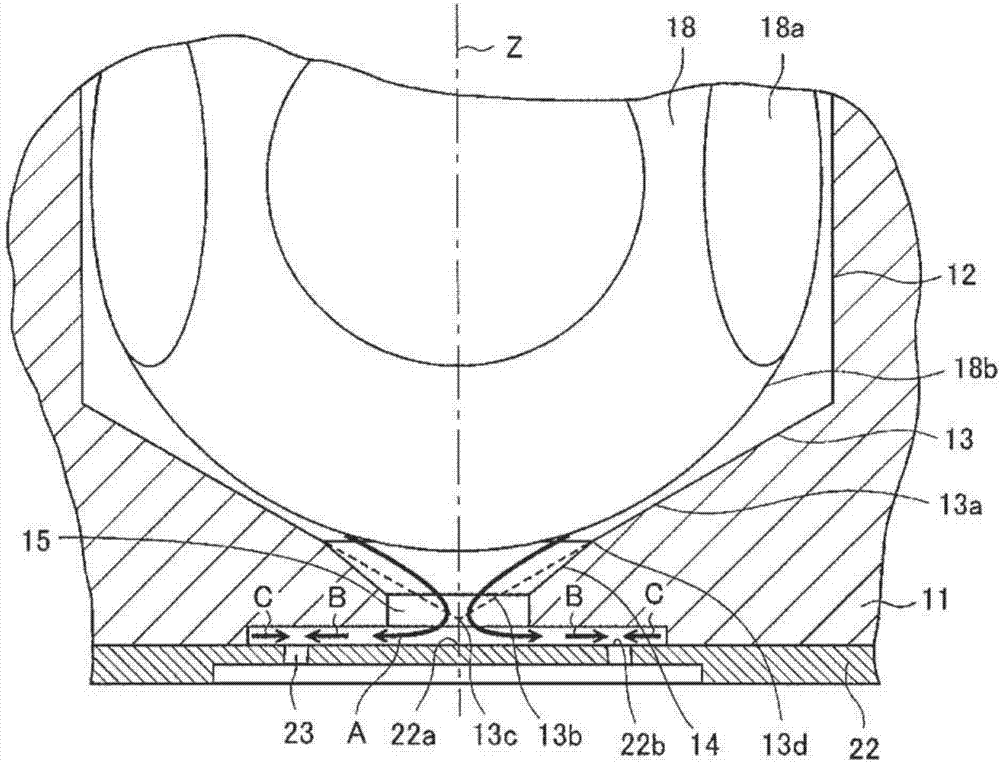
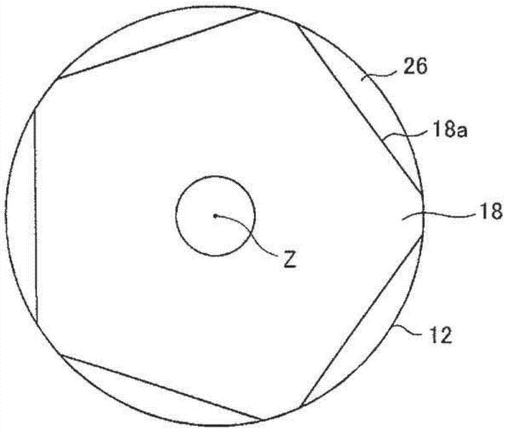
[0030] Next, the valve device of the fuel injection valve according to Embodiment 1 of the present invention will be described with reference to the drawings. figure 1 is a cross-sectional view of the fuel injection valve according to Embodiment 1 cut along a plane parallel to the central axis (indicated by Z in the figure), figure 2 is a partial cross-sectional view obtained by cutting the front end of the valve device on a plane parallel to the central axis, image 3 It is a partial cross-sectional view obtained by cutting the front end portion of the valve device along a plane perpendicular to the central axis. In addition, in each figure, the same code|symbol is attached|subjected to the same or corresponding part.

[0031] The fuel injection valve 1 includes an electromagnetic device that generates electromagnetic force, and a valve device that operates by energizing the electromagnetic device. The electromagnetic device includes: a two-stage cylindrical casing 2 that...

Embodiment approach 2

[0065] Figure 7 It is a partial cross-sectional view obtained by cutting the front end portion of the valve device according to Embodiment 2 of the present invention on a plane parallel to the central axis, Figure 8 is expressed in Figure 7 Top view of the orifice plate viewed from the side indicated by A-A in the valve arrangement shown. In addition, since the overall structure of the fuel injection valve according to the second embodiment is the same as that of the first embodiment, the figure 1 , omitting detailed descriptions of each part.

[0066] In the valve device according to the second embodiment, when the injection hole 23 is vertically projected on a plane perpendicular to the central axis Z, a straight line connecting the central axis Z and the inlet center 23a of the injection hole 23 ( Figure 8 L1 in the middle), and the straight line connecting the inlet center 23a of the nozzle hole 23 and the outlet center 23b of the nozzle hole 23 ( Figure 8 where ...

Embodiment approach 3

[0074] Figure 11 is a partial cross-sectional view obtained by cutting the front end portion of the valve device according to Embodiment 3 of the present invention in a direction parallel to the central axis, Figure 12 The part represented by A-A will Figure 11 A partial cross-sectional view of the front end of the valve assembly shown. also, Figure 12 In FIG. 3 , the nozzle holes 23 of the nozzle plate 22 are projected onto the valve ball 18 to show the positional relationship between the shape of the valve ball 18 and the nozzle holes 23 . The overall structure of the fuel injection valve according to Embodiment 3 is the same as that of Embodiment 1, so the figure 1 , omitting the detailed description of each part.

[0075] In the valve device according to Embodiment 3, the number of injection holes 23 is different from the number of slit surfaces 18 a. Five slit surfaces 18 a of the valve ball 18 are uniformly formed on the circumference of the valve body 16 . On...


PUM


Abstract

A valve device for a fuel injection valve (1), wherein the intersection point (13c) between the center line Z of the valve seat (11) and the apex of a hypothetical cone (13b) formed by extending a seating surface (13) toward the downstream side is positioned inside an aperture (15). Thus, after most of the fuel that has passed through a seat part (13a) converges at the aperture (15), the fuel reaches the upper surface of an injection hole plate (22) and smoothly changes to a flow toward the outer circumferential side, thereby minimizing the fuel pressure loss in this interval. Therefore, in this valve device for the fuel injection valve (1), a decrease in the fuel speed in the section (22b) directly above the injection hole is reduced, and atomization of the fuel spray is promoted.

Description

technical field [0001] The present invention relates to a valve device of a fuel injection valve for supplying fuel to an internal combustion engine of an automobile. Background technique [0002] In recent years, internal combustion engines are becoming FI (Fuel Injection: Fuel Injection), and fuel injection valves are increasingly used in small-displacement two-wheeled vehicles. The fuel injection valve includes an electromagnetic device that generates electromagnetic force, and a valve device that operates by energizing the electromagnetic device. The valve device has: a valve seat provided in the middle of a passage through which fuel flows and having an opening on the downstream side; ; and an orifice plate, which is disposed downstream of the opening of the valve seat. [0003] As a characteristic of fuel spray injected from a fuel injection valve, atomization of the spray is required, and various studies have been conducted accordingly. For example, in the valve de...

Claims


Application Information

Patent Timeline
Patent Type & Authority Applications(China)
IPC IPC(8): F02M61/18F02M51/06F02M51/08
CPCF02M61/1866F02M61/188F02M61/1853F02M51/061
Inventor 渡边恭辅福冨范久宗实毅平井学
Owner MITSUBISHI ELECTRIC CORP
Why Eureka
Try Eureka