
Container structure of floating humidifier

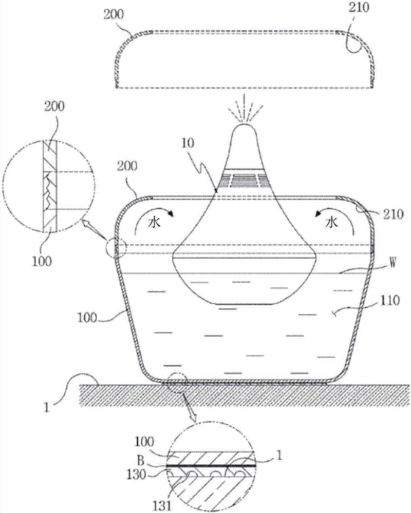
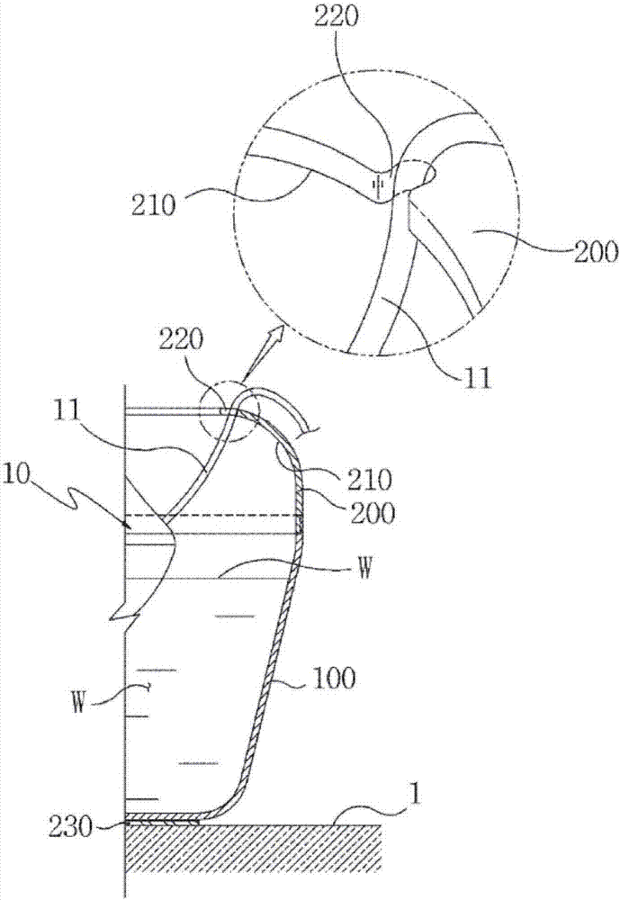
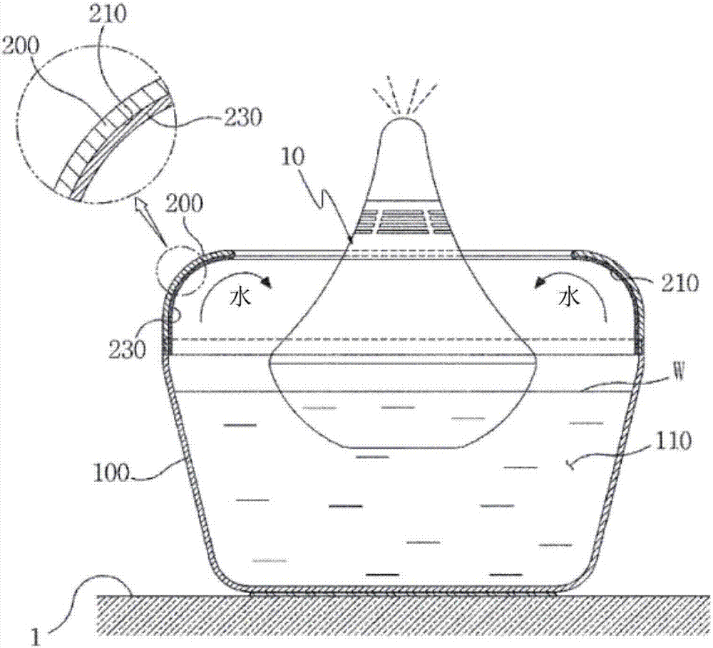
A humidifier and suspension technology, which is applied in the container structure field of the suspension humidifier, can solve problems such as damage to the tank and the suspension humidifier, movement of the suspension humidifier, and collision with the wall of the tank, so as to improve the stability of the setting and prevent Electric shock accidents and the effect of ensuring safety in use

Active Publication Date: 2017-08-18
KPC CORP
View PDF5 Cites 3 Cited by
  • Summary
  • Abstract
  • Description
  • Claims
  • Application Information

AI Technical Summary

Problems solved by technology

[0008] However, when the conventional floating humidifier uses a wired system using a power cord, the power cord is not fixedly installed, so there is a possibility that the floating humidifier may move or hit the wall of the tank due to the flow of the power cord.
[0009] Moreover, the water tank for suspending the suspension humidifier may fall or flow due to external force, and the water tank and the suspension humidifier may be damaged, and the water stored in the water tank may flow, and the water may overflow to the outside of the water tank. Worries, resulting in worries about electric shock accidents based on leakage

Method used


Image

  • Container structure of floating humidifier
  • Container structure of floating humidifier
  • Container structure of floating humidifier

Examples


Embodiment Construction

[0041] Hereinafter, preferred embodiments of the present invention will be described in detail with reference to the accompanying drawings.

[0042] Reference and attachment Figure 1 The advantages and features of the present invention, and the method for realizing the above advantages and advantages will become more clear with the embodiments described later in detail.

[0043] Moreover, the present invention is not limited to the embodiments disclosed below, but can be embodied in various forms. However, this embodiment makes the disclosure of the present invention complete, and it is useful to those of ordinary skill in the art to which the present invention belongs. Provided that the full scope of the invention is provided, the invention is defined by the scope of the claimed invention.

[0044] Also, in the course of describing the present invention, when it is judged that related known techniques and the like make the gist of the present invention unclear, a detailed d...


PUM


Abstract

In a water tank for a floating humidifier, movably provided in a state in which the floating humidifier floats in an accommodation space in which water is stored, a container structure of the floating humidifier, according to the present invention, comprises: a lower body of which the accommodation space opened upwards is formed therein and of which the lower surface to be put on a mounting surface is horizontally formed; and an upper body of which the lower end is correspondingly coupled to the upper end of the lower body and the upper end is molded to be bent as a curved surface toward the accommodation space so as to allow the water moving to the side by an external force to be put into the accommodation space again.

Description

technical field [0001] The present invention relates to a container structure of a suspension type humidifier. Specifically, the container is installed on an installation surface with a wide area. The container structure of the suspended humidifier for the stability of the setting and the safety of use. Background technique [0002] Generally, a humidifier is a device for supplying moisture to a dry room, and is classified into an ultrasonic humidifier using ultrasonic waves and a heating humidifier using a heater according to a humidification method. [0003] First, the ultrasonic humidifier uses the ultrasonic vibrator installed in the water tank to convert the water into fine water droplets, and then uses the air blower to spray the fine water droplets in an atomized state. On the contrary, the heating humidifier uses the heater installed in the water tank. After steaming the water with heat, a blower fan is used to spray steam in an atomized state. [0004] The above-m...

Claims


Application Information

Patent Timeline
Patent Type & Authority Applications(China)
IPC IPC(8): F24F6/12B65D25/14B65D25/20B65D25/28
CPCB65D25/14B65D25/20B65D25/28F24F6/12B05B17/0684B05B17/0646B05B17/06B01F23/2133B05B17/0615
Inventor 吴龙柱
Owner KPC CORP
Learn More