Coil arrangement and transformer with low inter-winding capacitance

A coil arrangement and transformer technology, applied in discontinuous variable inductors/transformers, transformer/inductor components, coils, etc., can solve problems such as increased power loss, damage to the performance of coil layout structures, and increased winding resistance.

Active Publication Date: 2019-01-11
国民太阳能有限责任公司
View PDF14 Cites 0 Cited by
  • Summary
  • Abstract
  • Description
  • Claims
  • Application Information

AI Technical Summary

Problems solved by technology

A particular problem in the case of high-frequency devices is the increased power loss at the winding ends due to increased contact resistance and thus impairing the performance of the coil arrangement
Typically, each end and solder joint between conductor segments adds significantly to winding resistance

Method used


Image

  • Coil arrangement and transformer with low inter-winding capacitance
  • Coil arrangement and transformer with low inter-winding capacitance
  • Coil arrangement and transformer with low inter-winding capacitance

Examples


Embodiment Construction

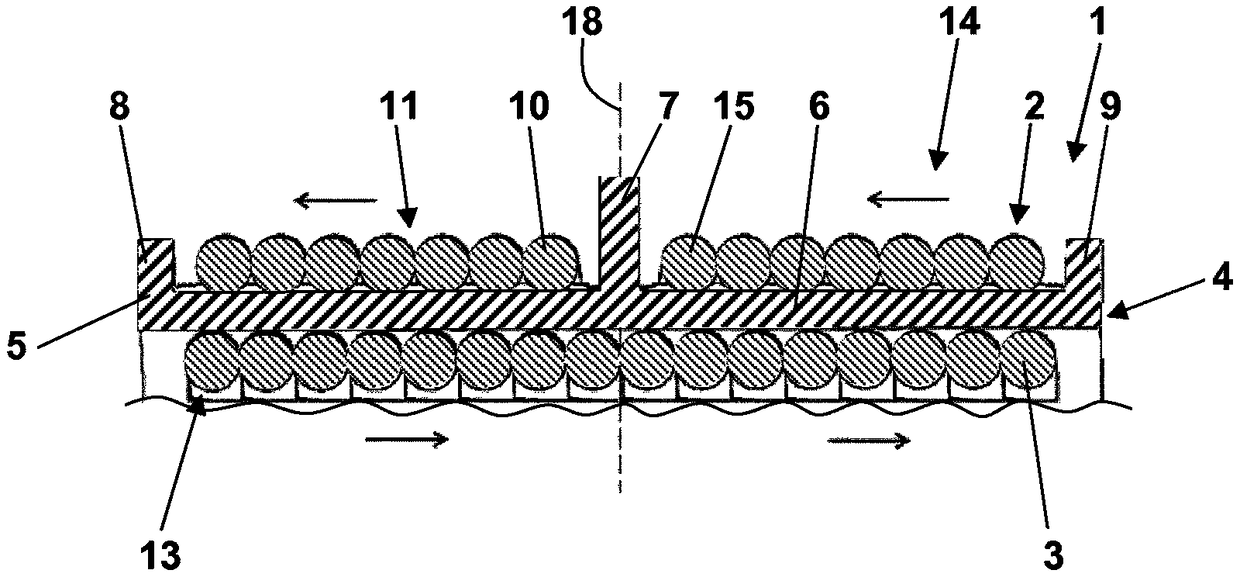
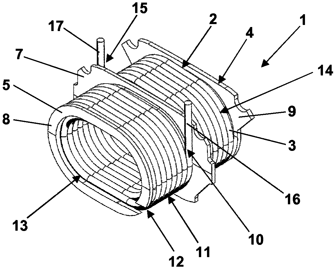
[0050] in accordance with figure 1 with 2 In the coil arrangement of , a single continuous conductor segment 2 formed of a solid wire 3 is wound within and around a bobbin 4 made of electrically insulating material 5 . The spool 4 comprises a tubular wall 6, a central flange 7, made of said material 5 and extending radially from the outside of the wall 6, and two end flanges 8 and 9, said two end flanges 8 and 9. Flanges 8 and 9 are also made of said material 5 and extend radially from the outside of wall 6 . Starting from the start 10 , the successive conductor segments 2 first form a first set of conductor windings 11 on the outside of the wall 6 . The continuous conductor segment 2 then passes through the opening 12 in the end flange 8 . The continuous conductor segments 2 then form a second set of conductor windings 13 at the inner side of the wall 6 . Next, the continuous conductor section 2 passes through the opening in the end flange 9 before it finally forms the th...


PUM


Abstract

A coil arrangement (1) with low interwinding capacitance is disclosed, comprising a bobbin (4) made of electrically insulating material (5) and comprising a tubular wall (6). The coil is mechanically supported by said bobbin (4) and comprises a first set of conductor windings (11) on the outside of said wall (6) and a second set of conductor windings (13) on the inside of said wall (6). ).

Description

technical field [0001] The invention relates to a coil arrangement. In particular, the invention relates to a coil arrangement exhibiting low inter-winding capacitance. Such a coil arrangement can be used in various applications including conductors and is especially intended for use in transformers. Background technique [0002] In a coil arrangement, the inter-winding capacitance results from the fact that a voltage drop across a coil in a coil arrangement causes a voltage to exist between adjacent individual conductor windings in the coil. The electrically insulating structure between these conductor windings acts as a dielectric forming some form of capacitor whose electrodes are adjacent conductor windings and which are loaded with the voltage between adjacent conductor windings. Thus, the dependence of the interwinding capacitance increases with increasing voltage between adjacent conductor windings. [0003] There are various known winding arrangements for coil arr...

Claims


Application Information

Patent Timeline
Patent Type & Authority Patents(China)
IPC IPC(8): H01F27/00H01F27/28H01F27/30
CPCH01F27/006H01F27/2823H01F27/306H01F5/02H01F27/29H01F27/325H01F2005/022H01F21/005H01F21/12H01F2005/006
Inventor 马雷克·里尔科M·卡科基马瑞斯·瓦尔恰克H·奥尔登坎普
Owner 国民太阳能有限责任公司
Why Eureka
Try Eureka