Stirring device for yoghourt production
A stirring device, technology of yogurt, applied in the direction of a mixer with a rotating stirring device, mixer accessories, transportation and packaging
Inactive Publication Date: 2017-08-22
上海正邻机电自动化设备有限公司
View PDF4 Cites 1 Cited by
- Summary
- Abstract
- Description
- Claims
- Application Information
AI Technical Summary
Problems solved by technology
[0004] Yogurt needs to be stirred after fermentation, but most of the equipment now only has the function of stirring
Method used
View moreImage
Smart ImageViewing Examples
Examples
Embodiment 2
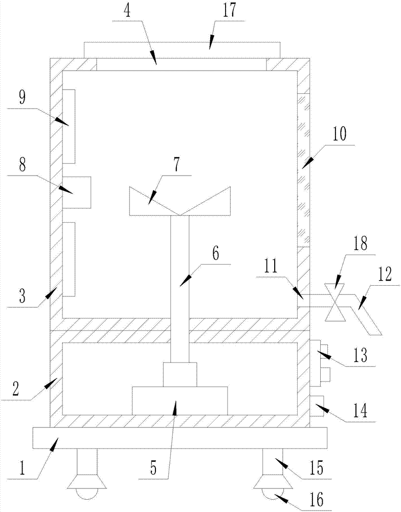
[0018] Embodiment 2: The effect of stirring yogurt can also be achieved by replacing the stirring blade with a folded stirring rod, and the other structures are the same as in Embodiment 1.
Login to View More PUM
 Abstract
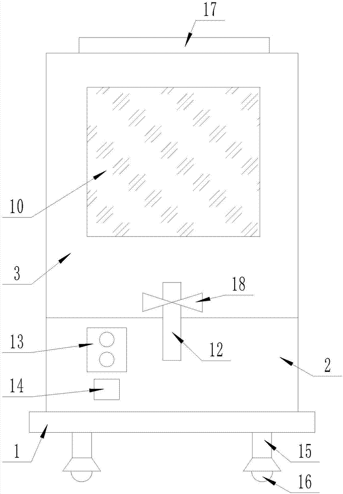
The invention discloses a stirring device for yoghourt production. The stirring device comprises a rectangular base, wherein a rectangular control box body is arranged on the upper surface of the rectangular base; a yoghourt bearing barrel is arranged on the upper surface of the rectangular control box body; a rectangular opening is formed in the upper surface of the yoghourt bearing barrel; a rotating motor of which a rotating end is upward is arranged at the center of the lower surface in the rectangular control box body; a rotating shaft which passes through the upper surface of the rectangular control box body and the lower surface of the yoghourt bearing barrel and extends into the yoghourt bearing barrel at the same time is arranged at the rotating end of the rotating motor; a stirring blade is arranged at the upper end of the rotating shaft; a waterproof temperature sensor and a group of heating sheets are arranged on the left side surface in the yoghourt bearing barrel; an observation opening is formed in the right side surface of the yoghourt bearing barrel; and sealed transparent glass is embedded into the observation opening. The stirring device has the beneficial effects that the fermented yoghourt can be fully stirred in the producing and processing process of the yoghourt, and an appropriate temperature can be controlled.
Description
technical field [0001] The invention relates to the field of yogurt processing, in particular to a stirring device for yogurt production. Background technique [0002] Yogurt is a kind of donkey milk product that uses donkey milk as raw material. After pasteurization, beneficial bacteria (starter) are added to donkey milk, and after fermentation, it is cooled and filled. [0003] The production process of yogurt can be summarized as ingredients, preheating, homogenization, sterilization, cooling, inoculation, filling, fermentation, stirring, packaging and post-ripening procedures. [0004] Yogurt needs to be stirred after fermentation, but most of the equipment now only has a stirring effect. If you can control the temperature of the yogurt at all times during the stirring process, you will produce better quality yogurt. Therefore it is necessary to design a stirring device for yoghurt production. Contents of the invention [0005] The purpose of the present invention i...
Claims
Login to View More Application Information
Patent Timeline
 IPC IPC(8): B01F7/18B01F15/00
CPCB01F27/90B01F35/2115B01F35/2215B01F2101/07
Inventor 田野
Owner 上海正邻机电自动化设备有限公司
Features
- R&D
- Intellectual Property
- Life Sciences
- Materials
- Tech Scout
- Unparalleled Data Quality
- Higher Quality Content
- 60% Fewer Hallucinations
Learn More Browse by: Latest US Patents, China's latest patents, Technical Efficacy Thesaurus, Application Domain, Technology Topic, Popular Technical Reports.
© 2025 PatSnap. All rights reserved.Legal|Privacy policy|Modern Slavery Act Transparency Statement|Sitemap|About US| Contact US: help@patsnap.com


