Methods and systems for prediction of sensor response time

A response time and sensor technology, applied in instruments, measuring devices, machines/engines, etc., can solve problems affecting emission quality, difficulty in meeting on-board diagnostic target completion rate, underestimation of smoke and dust, etc.

Active Publication Date: 2017-08-22
FORD GLOBAL TECH LLC
View PDF10 Cites 6 Cited by
  • Summary
  • Abstract
  • Description
  • Claims
  • Application Information

AI Technical Summary

Problems solved by technology

For example, for a soot sensor downstream of a particulate filter, if the average response time is higher than the actual response time, soot will be underestimated, potentially failing to detect soot leaking through a faulty filter into the exhaust stream, and adversely affecting Emission quality
Also, filter degradation may not be detected (e.g. due to high soot leakage)
Additionally, by discarding large amounts of data, it may be difficult to meet the requirements to complete OBD and meet the target completion ratio in a given drive cycle

Method used


Image

  • Methods and systems for prediction of sensor response time
  • Methods and systems for prediction of sensor response time
  • Methods and systems for prediction of sensor response time

Examples


Embodiment Construction

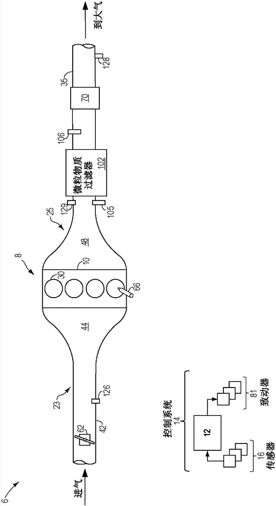
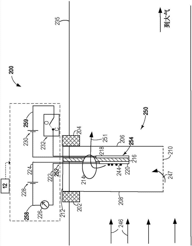
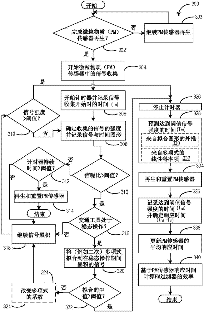
[0015] The following description relates to systems and methods for predicting the response time of a particulate matter (PM) sensor and resetting the PM sensor. In this example, the PM sensor is coupled to a figure 1 The engine system of the engine system shown. A PM sensor may be coupled to the exhaust passage upstream and / or downstream of the particulate matter filter. Due to the respiratory hazard of PM in the air, PM sensors are used to measure the concentration and / or flow of conductive soot particles in any combustion exhaust. exist figure 2 A detailed description of a PM sensor coupled to an exhaust passage is shown in . One example of the use of PM sensors in the automotive industry is for controlling or diagnosing emissions of regulated PM emissions of automobiles. The engine controller is configured to perform tasks such as image 3 A control routine of an example routine to predict the response time of the PM sensor based on the soot accumulation signal obtai...


PUM


Abstract

The invention relates to methods and systems for prediction of sensor response time. Methods and systems are provided for predicting response time of a particulate matter (PM) sensor and resetting the PM sensor upon completion of response time prediction, independent of actual or predicted soot load on PM sensor. Soot accumulation data collected during steady state vehicle operation may be fitted with a time-based polynomial function and sensor output and regeneration schedule may be estimated from the curve fit even if the overall signal is noisy.

Description

technical field [0001] The description generally relates to methods and systems for predicting response times of particulate matter (PM) sensors. Background technique [0002] Internal combustion engines can generate particulate matter (PM) and pollutants such as soot and aerosols that can be exhausted into the atmosphere. Various technologies have been developed to filter this PM before the exhaust gas is released into the atmosphere. As an example, to improve emissions compliance, a particulate filter (PF) may be included in the engine exhaust system. One or more PM sensors (also referred to as soot sensors) may be located upstream and / or downstream of a particulate filter (PF) and may be used to sense PM load on the filter, regulate regeneration of the filter, and / or or the function of a diagnostic filter. [0003] When included, a PM sensor may be used to sense a PM based on a correlation between a measured change in current and / or conductance at the sensor element an...

Claims


Application Information

Patent Timeline
Patent Type & Authority Applications(China)
IPC IPC(8): F01N11/00F01N9/00F01N3/023G01D18/00
CPCF01N3/023F01N9/002F01N11/00F01N2260/04F01N2560/05G01D18/00G01N15/0656G01N2015/0046G01M15/102
Inventor D·C·韦伯G·A·扎瓦茨基V·V·扎姆贝尔E·P·斯库尔斯Z·阿娜琪莎
Owner FORD GLOBAL TECH LLC
Why Eureka
Try Eureka