Systems and methods for vehicle evaporative emissions system diagnostics

a technology of evaporative emissions and diagnostics, applied in the direction of piston pumps, electric control, instruments, etc., can solve the problems of limiting the rate of pressure or vacuum development, prone to false failure of eonv test based on customer, false failure, etc., to achieve higher pressure in the fuel vapor system, facilitate the venting process, and raise the effect of lowering

Inactive Publication Date: 2017-12-07
FORD GLOBAL TECH LLC
View PDF1 Cites 8 Cited by
  • Summary
  • Abstract
  • Description
  • Claims
  • Application Information

AI Technical Summary

Benefits of technology

[0009]In one example, the vehicle system may comprise a body element such as a hood, a trunk, and / or a gull wing style door which may be raised and lowered based on operator demand. Pneumatic or screw motor cylinders may be present in the vehicle lift gate which may be used to draw in ambient air via an orifice. During raising of the hood or trunk, a canister vent valve of an engine evaporative emissions control system may be closed and a lift gate valve coupling the body element to the evaporative emissions control system may be opened such that the lift gate cylinders may draw out air from the fuel vapor system, creating a vacuum therein. Once a sufficient level of vacuum has built in the fuel vapor system, the fuel vapor system may be sealed and bleed-down of vacuum may be observed over a defined period of time. If the rate of vacuum decay is higher than an expected rate, it may be inferred that undesired evaporative emissions may be present. If the vehicle hood or trunk is lowered during the test, the lift gate valve may have to be re-opened, the current diagnostic test may be terminated, and the fuel vapor system may be vented. Along with the lift gate valve, the canister vent valve may be opened to facilitate the venting process and may be subsequently closed within a short time while the hood or trunk is still in the process of being lowered. The closing of the lift gate valve and the opening and closing of the canister vent valve may cause air to be compressed into the fuel vapor system, thereby creating a higher pressure in the fuel vapor system. The higher pressure may then be used for a further diagnostic routine to detect any undesired emissions in the evaporative emissions control system. If the rate of higher pressure decay is higher than expected, it may be inferred undesired evaporative emissions are present in the system.
[0010]In this way, a cylinder coupled to a vehicle body element such as a hood, or a trunk may be used to apply vacuum and / or positive pressure in a fuel vapor system. By using this vacuum and / or higher pressure generated by the lift gate cylinders, detection of undesired emissions in the evaporative emissions control system may be opportunistically carried out without dependence on ambient temperature and duration of engine key-off. In addition, the need of dedicated vacuum / positive pressure pumps for providing the pressure is reduced. The technical effect of using lift gate cylinders coupled to a vehicle hood or trunk for evaporative emissions control system diagnostic test is that the test may be carried out both during raising of the hood or trunk (using the vacuum generated in the process) and during lowering of the hood or trunk (using the positive pressure generated in the process). By coupling the lift gate cylinders directly to a vent line of the fuel vapor system, a time required for attaining the desired vacuum or higher pressure may be lowered and an evaporative emissions control system diagnostic test may be carried out within a short time of engine operation, such as in the limited engine-on time of a hybrid vehicle. As a result, a larger number of diagnostics tests may be carried out within a drive cycle, improving the completion ratio for the evaporative emissions control system monitoring. Therefore, by using a lift gate cylinder for evaporative emissions control system diagnostics, engine emissions compliance may be improved.

Problems solved by technology

However, the EONV test is prone to false failures based on customer driving and parking habits.
For example, a refueling event that fills the fuel tank with relatively cool liquid fuel followed by a short ensuing trip may fail to heat the fuel bulk mass and may result in a false fail if an EONV test is run.
During mild weather conditions, the ambient temperature may restrict the amount of heating or cooling of the fuel tank following engine shut-off, and thus limit the rate of pressure or vacuum development.
As such, in a case wherein a pressure build does not reach the expected threshold, the subsequent vacuum build may additionally not reach expected threshold level in the time allotted for the EONV test based on available battery charge.
This may result in a false-fail condition, leading to potentially unnecessary engine service.
However, the inventors herein have recognized potential issues with such a method.
For example, the use of an external pump introduces additional costs, occupies additional space in the vehicle, and includes the potential for malfunction.
However, the inventors have additionally recognized a potential issue with such a method.
Fuel vapors routed to the canister may increase the loading state of the canister, which may in some cases lead to an increase in bleed emissions from the canister depending on the adsorbent capacity of the canister.
However, the inventors have further recognized a potential issue with such a method.
For example, while the method may serve to facilitate an increased level of vacuum during the vacuum build portion of an EONV test, the portion of the EONV test wherein a pressure build is monitored is not able to be manipulated by such a method.
If the rate of vacuum decay is higher than an expected rate, it may be inferred that undesired evaporative emissions may be present.

Method used


Image

  • Systems and methods for vehicle evaporative emissions system diagnostics
  • Systems and methods for vehicle evaporative emissions system diagnostics
  • Systems and methods for vehicle evaporative emissions system diagnostics

Examples


Embodiment Construction

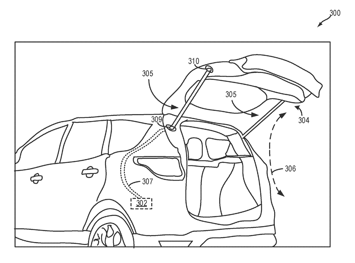
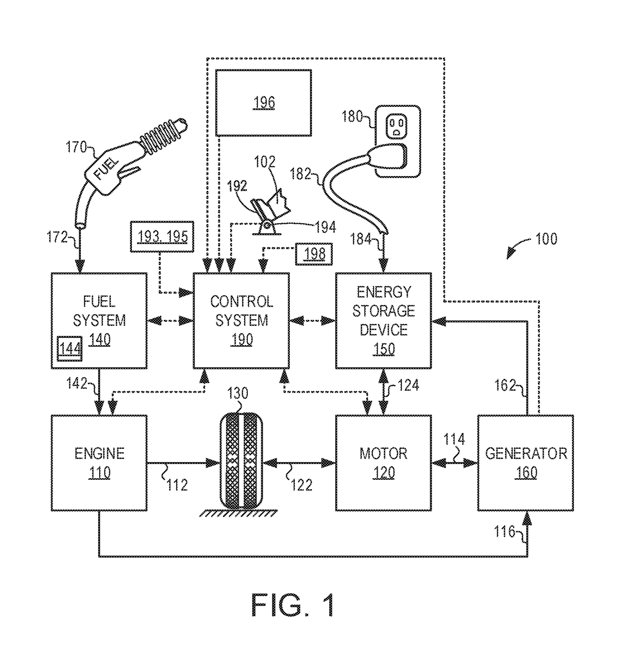
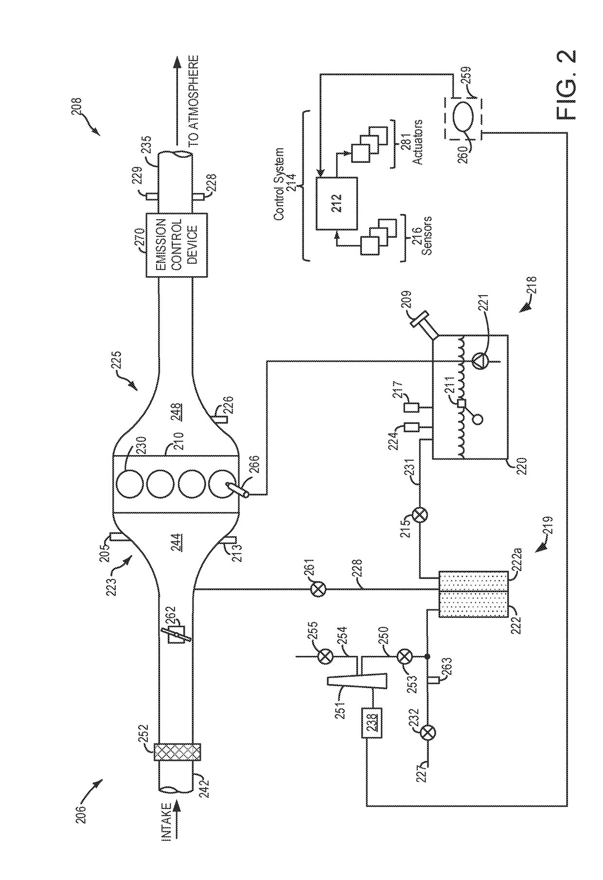
[0018]The following description relates to systems and methods for using vacuum and higher pressure generated via lift gate cylinders for diagnostics of an evaporative emissions control system. An example vehicle system with an engine and an electric motor is shown in FIG. 1 and a detailed description of the engine system comprising an evaporative emissions control system and fuel system is shown in FIG. 2. An example of lift gate cylinders coupled to a vehicle trunk used for the evaporative emissions control system diagnostics is shown in FIG. 3. An engine controller may be configured to perform a control routine, such as the example routines of FIGS. 4 and 5 for carrying out the evaporative emissions control system diagnostic tests during opening and subsequent closing of a vehicle body element such as a hood or a trunk, using lift gate cylinders. An example of the diagnostics routine is shown with reference to FIG. 6.

[0019]Turning now to the figures, FIG. 1 illustrates an example...


PUM


Abstract

Methods and systems are provided for conducting a diagnostic routine of the fuel vapor system using pressure generated by raising or lowering a vehicle body element such as a hood or a trunk. In one example, by utilizing lift gate cylinders coupled to the hood or trunk, during raising a hood or trunk, the fuel vapor system may be evacuated and during lowering the hood or trunk, the fuel vapor system may be pressurized. A change in vacuum or higher pressure in the fuel vapor system may be monitored over a time period to detect any undesirable evaporative emissions from the fuel vapor system.

Description

FIELD[0001]The present description relates generally to methods and systems for actively pressurizing or evacuating a vehicle evaporative emissions control system and fuel system to test for the presence of undesired evaporative emissions.BACKGROUND / SUMMARY[0002]Vehicle evaporative emission control systems may be configured to store fuel vapors from fuel tank refueling and diurnal engine operations, and then purge the stored vapors during a subsequent engine operation. In an effort to meet stringent federal emissions regulations, emission control systems may need to be intermittently diagnosed for the presence of undesired evaporative emissions that could release fuel vapors to the atmosphere.[0003]Undesired evaporative emissions may be identified using engine-off natural vacuum (EONV) during conditions when a vehicle engine is not operating. In particular, a fuel system and evaporative emissions control system may be isolated at an engine-off event. The pressure in such a fuel syst...

Claims


Application Information

Patent Timeline
Patent Type & Authority Applications(United States)
IPC IPC(8): F02M25/08G01M3/02F04B35/00F04B39/12F02D41/00F02D41/26G01M3/26F04B53/14
CPCF02M25/0818F02M25/089F02M25/0854F02M25/0836F04B39/12G01M3/26F04B35/008F02D41/26F02D41/003G01M3/025F04B53/14F02D41/22F02D2041/225F04B33/00F04B37/00F04B39/0005
Inventor LUCKA, KEVINYANG, DENNIS SEUNG-MANDUDAR, AED M.AGHILI, MOHAMMAD R.
Owner FORD GLOBAL TECH LLC
Why Eureka
Try Eureka