vehicle temperature display

A display device, vehicle technology, applied in the direction of temperature measurement in motors, temperature measurement of moving fluids, thermometers, etc., can solve problems such as occupant anxiety

Inactive Publication Date: 2019-10-08
MAZDA MOTOR CORP
View PDF5 Cites 0 Cited by
  • Summary
  • Abstract
  • Description
  • Claims
  • Application Information

AI Technical Summary

Problems solved by technology

Such a change in cooling water temperature itself is not particularly problematic, but if the display of the water temperature display section changes drastically together with the cooling water temperature, it may cause uneasiness to the occupants.

Method used


Image

  • vehicle temperature display
  • vehicle temperature display
  • vehicle temperature display

Examples


Embodiment Construction

[0082] Hereinafter, embodiments of the present invention will be described with reference to the drawings.

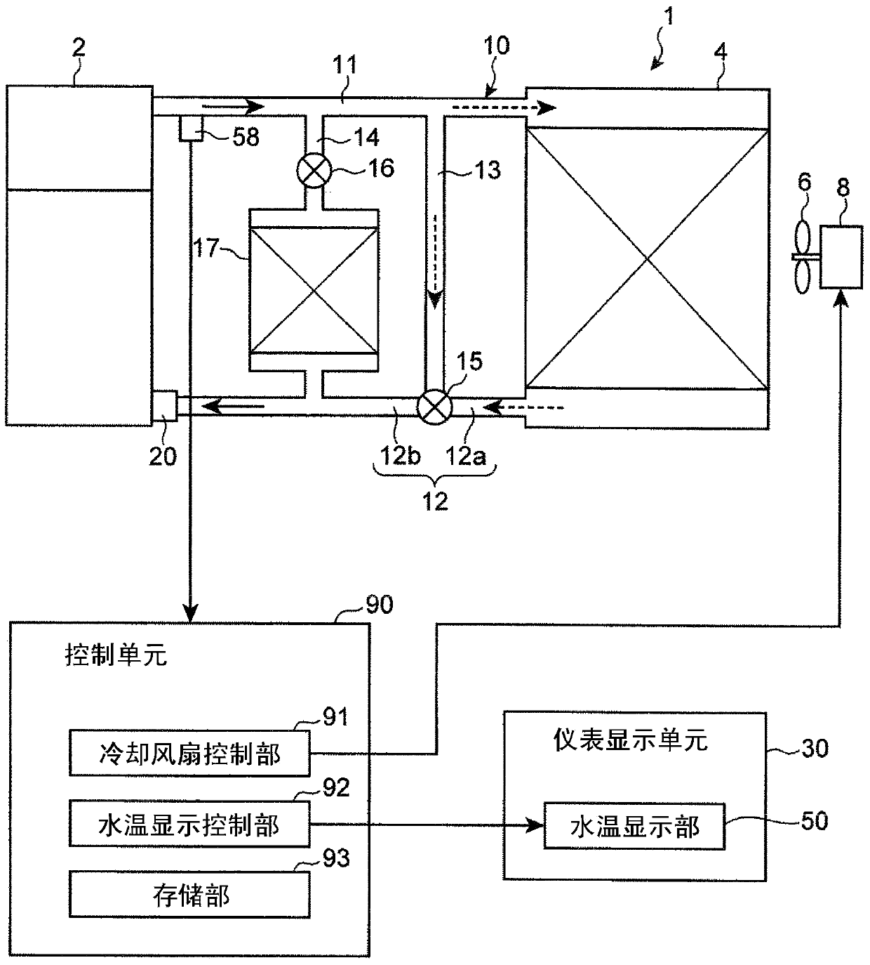
[0083] Such as figure 1 As shown, the engine cooling system 1 includes: a flow path 10 for cooling water of the engine 2 ; a radiator 4 for cooling the cooling water flowing through the flow path 10 ; and a water pump 20 provided in the flow path 10 .

[0084] The cooling water flowing through the flow path 10 is cooled by the vehicle running wind when passing through the radiator 4 , or is forcibly cooled by the cooling fan 6 rotationally driven by the motor 8 as needed.

[0085] The water pump 20 is connected with the crankshaft of the engine 2 through a timing belt. Thereby, the water pump 20 can be driven by driving the engine 2 , and the cooling water in the flow path 10 can be circulated by the driving of the water pump 20 .

[0086] The flow path 10 is provided with: a first passage 11 for introducing cooling water from the engine 2 side to the radiator 4 side;...


PUM


Abstract

The present invention provides a temperature display device for a vehicle that suppresses occupant's sense of uneasiness caused by an excessive change in the temperature display of the cooling water in the vehicle temperature display device that displays the temperature of the cooling water of the engine and provides a more specific temperature display than before. show. The device is provided with: a temperature detecting unit (58) for detecting the temperature of cooling water of the engine (2), and the engine is in the first state of circulating through the radiator (4) and bypassing by opening and closing the thermostat (15). The radiator (4) is switched between the second state of circulation; the display part (50) that displays the cooling water temperature; and the display of the display part (50) is controlled based on the detected temperature detected by the temperature detection part (58). When the control unit (90) detects that the temperature (Ta) changes in a predetermined first temperature range (P4) in which the thermostat (15) is in an open state, the control unit (90) makes the display unit (50) display the temperature ( Tb) changes slowly compared to the change of detection temperature (Ta).

Description

technical field [0001] The present invention relates to a temperature display device for a vehicle that displays the temperature of cooling water of an engine. Background technique [0002] Generally, a thermostat is provided in an engine cooling system that circulates cooling water between the engine and the radiator. In such an engine cooling system, as the flow path starting from the engine and returning to the engine, a flow path passing through the radiator and a flow path bypassing the radiator are provided, and the switching of these flow paths is performed by opening and closing the thermostat. Switches between a first state in which the cooling water of the engine circulates through the radiator and a second state in which it circulates around the radiator. [0003] As a thermostat installed in an engine cooling system, a thermostat of a type that is opened and closed by expansion and contraction of a heat-expandable material such as wax is widely used. In this ki...

Claims


Application Information

Patent Timeline
Patent Type & Authority Patents(China)
IPC IPC(8): F01P11/16
CPCF01P11/16G01K1/02G01K13/02G01K2205/00G01K13/026B60Y2400/302B60Y2400/92G01M15/048
Inventor 渡濑博之
Owner MAZDA MOTOR CORP
Why Eureka
Try Eureka