Clutch with limiting function

A clutch and centrifugal body technology, applied in the field of clutches, can solve problems such as serious power loss and unstable performance

Inactive Publication Date: 2017-08-22
姜建中
View PDF0 Cites 0 Cited by
  • Summary
  • Abstract
  • Description
  • Claims
  • Application Information

AI Technical Summary

Problems solved by technology

In actual use, the performance of the above-mentioned lever centrifugal clutch is unstable, and sometimes the power loss is relatively serious

Method used


Image

  • Clutch with limiting function
  • Clutch with limiting function
  • Clutch with limiting function

Examples


Embodiment 1

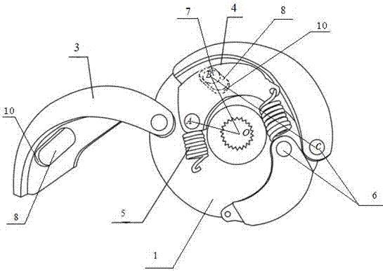
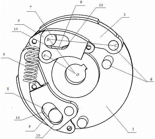
[0029] combined with figure 1 The said clutch with limit is provided with two or more groups of cylinders on the disk surface of the driving disc 1, and the roots of the cylinders are all provided with steps, and each group of cylinders includes centrifugal body positioning columns and special-shaped Lever positioning column, the centrifugal body positioning column is close to the edge, and the special-shaped lever positioning column is arranged on the inner side of the centrifugal body positioning column; one end of the centrifugal body 3 is movably socketed on the centrifugal body positioning column, and the movable body of the centrifugal body 3 The other end of the shaft is provided with a concave groove 8; the bottom of the special-shaped lever 4 is provided with a protruding body 7, and the protruding body 7 enters the inside of the centrifuge body 3 concave groove 8. One end of the special-shaped lever 4 is movably socketed on the special-shaped lever positioning column...


PUM


Abstract

The invention discloses a clutch with a limiting function. By means of the structure, the combination condition of a centrifugal body and a driven disc is limited, and therefore the use safety of the clutch is increased. Through the interaction of a special-shaped lever and the centrifugal body, the limiting function is added, and excessive wear and use in power transmission in the prior art are effectively reduced. A friction material of the centrifugal body of the clutch is worn to the scrap degree and cannot continue to be used. According to the clutch, the structure is simple, manufacturing and maintaining are convenient, and stability performance is improved.

Description

technical field [0001] The invention relates to a clutch, in particular to a clutch with a limit. Background technique [0002] Existing lever centrifugal clutch, its basic structure is by: driving plate, centrifuge body, special-shaped lever, positioning column (divided into double positioning column or single positioning column. Double positioning column: centrifugal body positioning column and special-shaped lever positioning column, And the positioning column of the special-shaped lever is set inside the positioning column of the centrifugal body. Single positioning column: the centrifugal body and the special-shaped lever are socketed on the same positioning column), a driven plate and a tension spring. When the speed of the prime mover reaches the set speed, the centrifugal body is combined with the driven plate through the action of centrifugal force, and the torque (power) is transmitted. When the rotation speed is lower than the set rotation speed (starting rotatio...

Claims


Application Information

Patent Timeline
Patent Type & Authority Applications(China)
IPC IPC(8): F16D43/18
CPCF16D43/18F16D2043/145
Inventor 姜建中
Owner 姜建中
Why Eureka
Try Eureka