Flying wing type double-duct vertical taking-off and landing aircraft

A technology for vertical take-off and landing and aircraft, which is applied in the aviation field, can solve the problems of fixed-wing aircraft not being able to take off and land vertically, fixed-wing aircraft with slow flight speed and low flight efficiency, and achieves increased power, strong practicability and high flight efficiency. Effect

Inactive Publication Date: 2017-08-25
张飞
View PDF0 Cites 38 Cited by
  • Summary
  • Abstract
  • Description
  • Claims
  • Application Information

AI Technical Summary

Problems solved by technology

[0003] The purpose of the present invention is to design a kind of advantage that can effectively integrate the above aircrafts for most of the fixed-wing aircrafts on the market can not take off and land, can not hover in the air and fixed-wing aircrafts flying speed is slow, and flight efficiency is low. A new aircraft that overcomes its shortcomings to a certain extent

Method used


Image

  • Flying wing type double-duct vertical taking-off and landing aircraft
  • Flying wing type double-duct vertical taking-off and landing aircraft
  • Flying wing type double-duct vertical taking-off and landing aircraft

Examples


Embodiment Construction

[0019] The present invention will be further described below in conjunction with the accompanying drawings.

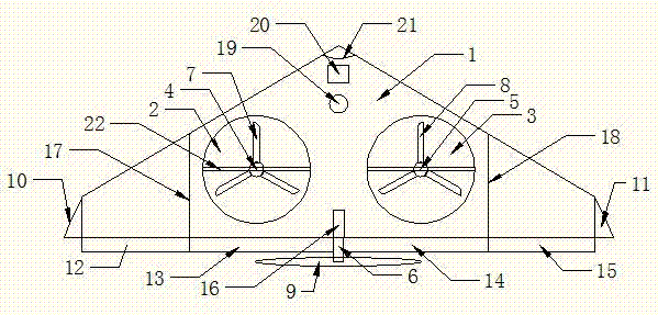
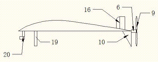
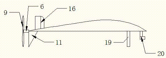
[0020] The utility model relates to a flying-wing double-duct aircraft capable of vertical take-off and landing. Such as Figure 1 , which mainly consists of five parts. The first part is the fuselage 1, the second part is the No. 1 ducted engine 4, the No. 2 ducted engine 5 and the rear engine 6, the third part is the vertical stabilizer 16, the No. 1 horizontal stabilizer 12, the No. 2 horizontal stabilizer 13, No. 3 horizontal stabilizer 14, No. 4 horizontal stabilizer 15, No. 1 winglet 10, No. 2 winglet 11. Such as figure 2 As shown, the fourth part is a support rod 19, and the fifth part is an external pan / tilt and camera or photoelectric sensor 20.

[0021] Such as figure 1 As shown, the fuselage 1 is a flying wing type, which is an isosceles triangle from a top view. The fuselage 1 is foldable, and the No. 1 folding line 17 and the No. 2 folding line 18 ar...


PUM


Abstract

A flying-wing double-ducted vertical take-off and landing aircraft. It mainly consists of five parts. The first part is the fuselage 1, the second part is the No. 1 ducted engine 4, the No. 2 ducted engine 5 and the rear engine 6, the third part is the vertical tail 16, the No. 1 horizontal tail 12, the No. 2 horizontal tail 13, No. 3 horizontal stabilizer 14, No. 4 horizontal stabilizer 15, No. 1 winglet 10, No. 2 winglet 11. The fourth part is the support rod 19 , and the fifth part is the externally mounted pan/tilt head and the camera or photoelectric sensor 20 . The fuselage 1 is a flying wing type, the fuselage 1 can be folded, and the fold line 17 and the fold line 2 18 are the folding points of the fuselage. There are No. 1 duct 2 and No. 2 duct 3 distributed on the fuselage 1. No. 1 ducted engine 4 and No. 2 ducted engine 5 are located in the center of No. 1 duct 2 and No. 2 duct 3, respectively, and are connected by connecting The rod 22 is fixed. The No. 1 ducted engine 4 and the No. 2 ducted engine 5 are respectively equipped with a No. 1 propeller 7 and a No. 2 propeller 8 . The rear engine 6 is located in the center of the tail of the fuselage 1 , and a rear propeller 9 is installed on the rear engine 6 . The No. 1 horizontal stabilizer 12 , the No. 2 horizontal stabilizer 13 , the No. 3 horizontal stabilizer 14 , and the No. 4 horizontal stabilizer 15 of the aircraft are respectively located at the rear of the fuselage 1 . The No. 1 winglet 10 and the No. 2 winglet 11 of the aircraft are located on the left and right sides of the fuselage 1 respectively, and are bent downward. The vertical tail 16 of the aircraft is located in the middle of the tail of the fuselage 1 , on the upper part of the fuselage 1 . The support rod 19 is located in the middle of the front part of the fuselage 1 , and is located in the lower part of the fuselage 1 . The camera or photoelectric sensor is located in the middle of the front of the body 1 and is installed under the body 1 . The sweep angle 21 is the sweep angle of the flying wing fuselage 1 .

Description

technical field [0001] The invention relates to a flying-wing double-duct aircraft capable of vertical take-off and landing. Mainly in the field of aviation. It can be widely used in aerial photography, aviation, firefighting, patrol, agriculture, express delivery, unmanned anti-submarine, model aircraft, etc. Background technique [0002] In recent years, with the rapid development of consumer drones and small and medium-sized aircraft, civilian aircraft are getting closer to life, and there are more and more types of aircraft. Most of the aircraft in the civilian market are small and medium-sized aircraft. And the aircraft is mainly divided into two categories: fixed-wing aircraft and multi-rotor aircraft. Both of them have inevitable defects: fixed-wing aircraft have high flight efficiency, but the take-off and landing methods are complex, cannot take off and land vertically, and the flight speed cannot be too small; multi-rotor aircraft can take off and land vertica...

Claims


Application Information

Patent Timeline
Patent Type & Authority Applications(China)
IPC IPC(8): B64C1/00B64C27/20B64C29/00
CPCB64C1/0009B64C27/20B64C29/00B64C2001/0045
Inventor 张飞
Owner 张飞
Why Eureka
Try Eureka