Non-disturbance rapid switching simulation test system

A simulation test system, fast switching technology, applied in circuit breaker testing, instruments, measuring devices, etc., can solve the problems of motor restart, current detection influence, no medium voltage side, etc., to prevent the expansion of accidents, avoid power outages, simple structure

Active Publication Date: 2017-08-25
ANHUI HEKAI ELECTRICAL TECH CO LTD
View PDF7 Cites 2 Cited by
  • Summary
  • Abstract
  • Description
  • Claims
  • Application Information

AI Technical Summary

Problems solved by technology

In response to these existing power grid operation problems, the company has developed and manufactured an intelligent dual power switching device, and has built a test system for simulating on-site operating conditions for different fault characteristics of the external network and the internal network. This simulation test system can be real Test the reliability and stability of the basic functions of the intelligent dual power switching device, which can fundamentally solve the problems that affect production, such as motor restart, contactor release, and inverter protection exiting operation caused by voltage sags
[0003] However, there are the following problems in operation: ①There is no load on the medium voltage side, and the current of the motor and lamps on the low voltage side is used as the load current, so the load current on the medium voltage side is small, which affects the current detection; ②The artificially simulated two-stage medium and low voltage The outgoing line is from the incoming line of the same voltage, which cannot simulate the actual operating conditions in all aspects

Method used


Image

  • Non-disturbance rapid switching simulation test system

Examples


Embodiment Construction

[0014] In order to make the technical means, creative features, goals and effects achieved by the present invention easy to understand, the present invention will be further described below in conjunction with specific illustrations.

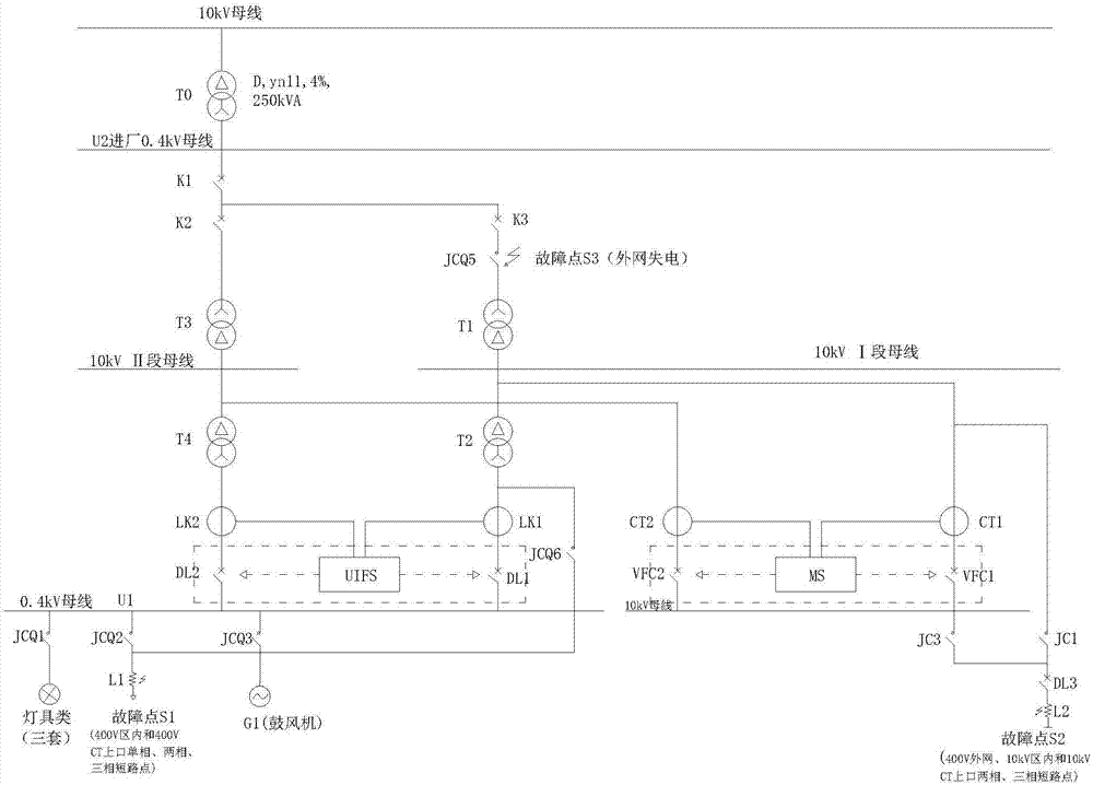
[0015] Such as figure 1 As shown, a non-disturbance fast switching simulation test system, including switch K1, switch K2 connected to the 400V bus, transformer T1, transformer T2, transformer T3, transformer T4, fast switch DL1, fast switch DL2, low-voltage contactor JCQ2 , low-voltage contactor JCQ5, low-voltage reactor L1, medium-voltage reactor L2, medium-voltage circuit breaker DL3, medium-voltage contactor JC1, power incoming circuit breaker module VFC1, power incoming circuit breaker module VFC2; the medium and low voltage of the system The outgoing line is led out by 4 transformers, the 400V incoming line is divided into two, and it is raised to 10KV through T1 and T3 transformers, and two sections of 10KV outgoing lines are simulated, a...


PUM


Abstract

The invention relates to a non-disturbance rapid switching simulation test system. The system comprises a switch K1 connected with a 400V bus, a switch K2, a transformer T1, a transformer T2, a transformer T3, a transformer T4, a rapid switch DL1, a rapid switch DL2, a low voltage contactor JCQ2, a low voltage contactor JCQ5, a low voltage reactor L1, a middle voltage reactor L2, a middle voltage breaker DL3, a middle voltage contactor JC1, a power source wire incoming breaker module VFC1 and a power source wire incoming breaker module VFC2, wherein middle and low voltage outgoing wires of the system are led out through the four transformers, a 400V incoming line is divided into two, the voltage is boosted to 10KV through the transformers T1 and T3, two segments of 10KV outgoing wires are simulated, the voltage is reduced to 400V through the transformers T2 and T4, two segments of 400V outgoing wires are simulated, fault simulation is carried out through the middle voltage contactor JC1, the low voltage contactor JCQ2, the middle voltage reactor L2 and the low voltage reactor L1, artificial interphase and relative short circuit is realized, and common operation problems of field loads are simulated.

Description

technical field [0001] The invention relates to the technical field of a power system dual power supply switching fault simulation platform, in particular to a non-disturbance fast switching simulation test system. Background technique [0002] In the medium and low-voltage power grid, when the system of any voltage level of the external power supply is short-circuited, the voltage of the entire low-voltage power grid will drop, and the higher the voltage level of the short-circuited system, the greater the impact area. In response to these existing power grid operation problems, the company has developed and manufactured an intelligent dual power switching device, and has built a test system for simulating on-site operating conditions for different fault characteristics of the external network and the internal network. This simulation test system can be real Testing the reliability and stability of the basic functions of the intelligent dual power switching device can funda...

Claims


Application Information

Patent Timeline
Patent Type & Authority Applications(China)
IPC IPC(8): G01R31/327G01R31/02
CPCG01R31/3275G01R31/3278G01R31/50
Inventor 解晓峰
Owner ANHUI HEKAI ELECTRICAL TECH CO LTD
Why Eureka
Try Eureka