Lens adjusting device

An adjustment device and lens technology, applied in the field of projectors, can solve the problems of affecting the accuracy of adjustment, poor adjustment effect, easy deflection of the lens adjustment device, etc., so as to achieve improved adjustment accuracy, good applicability, and simple and convenient adjustment process. Effect

Active Publication Date: 2017-08-25
HISENSE VISUAL TECH CO LTD
View PDF3 Cites 11 Cited by
  • Summary
  • Abstract
  • Description
  • Claims
  • Application Information

AI Technical Summary

Problems solved by technology

[0005] The present invention provides a lens adjustment device to solve the problem that the existing lens adjustment device is easily deflected when applied to the lens adjustment of a projector, which affects the adjustment accuracy and poor adjustment effect

Method used


Image

  • Lens adjusting device
  • Lens adjusting device
  • Lens adjusting device

Examples


Embodiment Construction

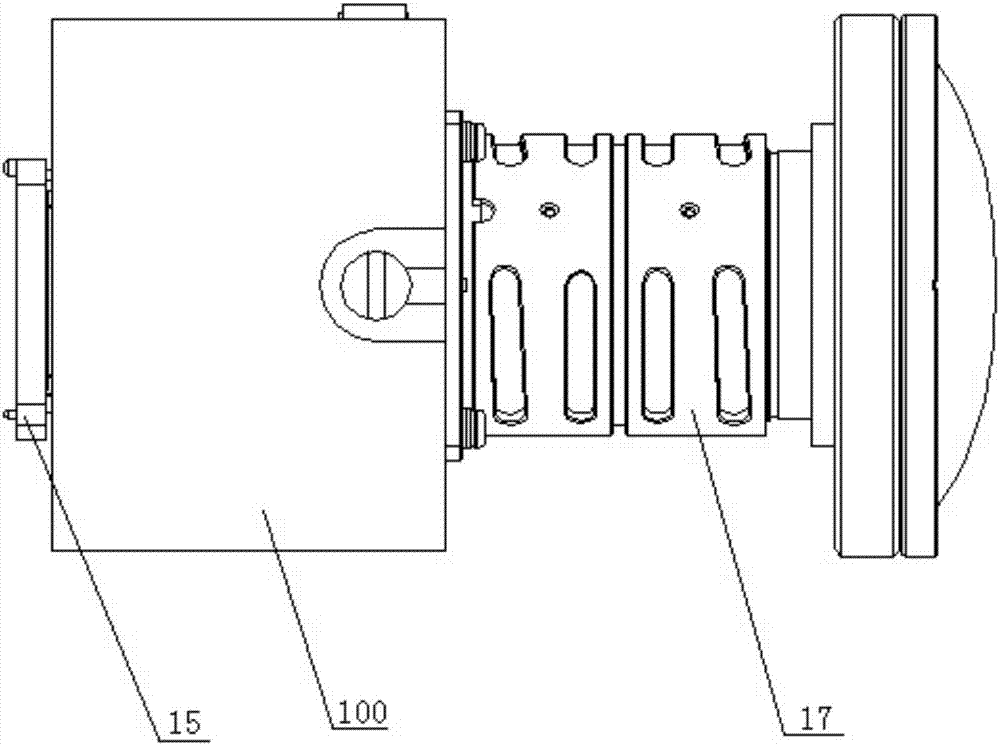
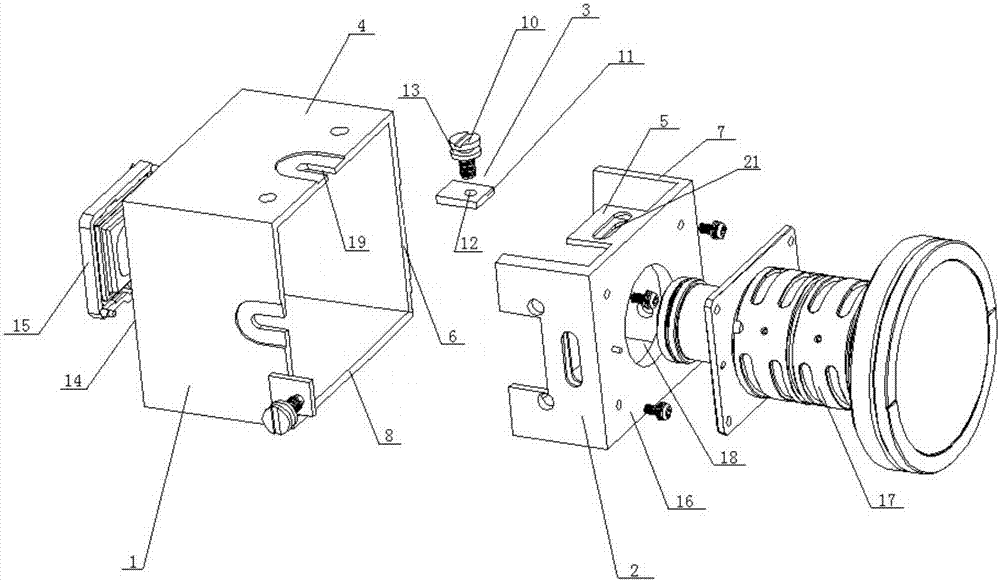
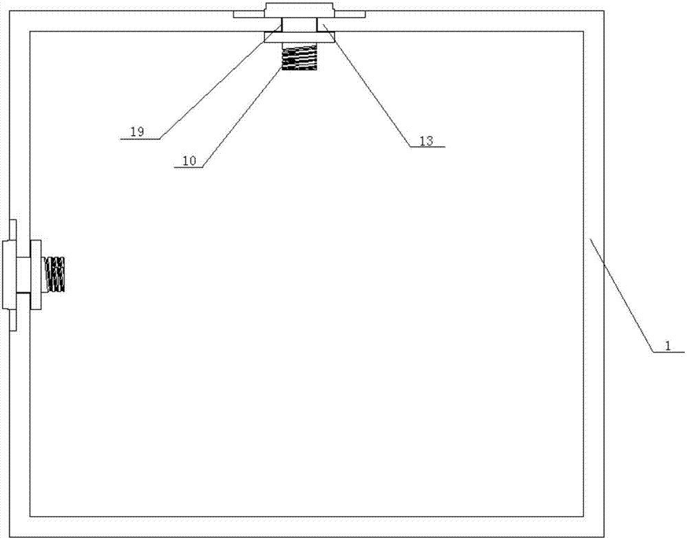
[0028] see Figure 1 to Figure 7 , figure 1 A schematic structural diagram of assembling a digital micromirror device and a lens using a lens adjustment device provided by an embodiment of the present invention. figure 2 for figure 1 An exploded diagram of . image 3 for figure 2 Schematic diagram of the assembly of the center light machine housing and adjustment components. Figure 4 for figure 2 Schematic diagram of the assembly of the middle lens bracket and adjustment components. Figure 5 for figure 2 Schematic diagram of the cooperation between the middle lens bracket and the adjustment parts. Image 6 for figure 2 Schematic diagram of the assembly of the medium lens bracket and lens. Figure 7 for figure 2 Schematic diagram of the structure of the adjusting screw. combine Figure 1 to Figure 7 It can be seen that the lens adjusting device 100 includes: an optical machine housing 1 , a lens holder 2 and a plurality of adjusting components 3 .

[0029] ...


PUM


Abstract

The invention discloses a lens adjusting device which comprises a light machine shell, a lens bracket and a sliding adjuster. The sliding adjuster includes at least two horizontal adjusting rods, at least two vertical adjusting rods, at least two horizontal rails parallel to each other and at least two vertical sliding rails parallel to each other. Each of the horizontal rails is equipped with a horizontal adjusting rod, and each of the vertical sliding rails is equipped with at least one vertical adjusting rod. One end of each of the horizontal adjusting rod is fixedly installed at a side wall of one side of the lens bracket, and the other end is fixedly installed to a side wall of the other side of the lens bracket. One end of each of the vertical adjusting rod is fixedly installed at a top wall of the light machine shell, and the other end is fixedly installed to the bottom wall of the light machine shell. When the lens adjusting device is used to adjust a deviation between a lens and a digital micro mirror device of an optical engine, the lens adjusting device can not deflect by itself, the adjusting precision is more accurate, and the applicability is better.

Description

technical field [0001] The invention relates to the technical field of projectors, in particular to a lens adjusting device. Background technique [0002] After the optical engine of the projector is assembled with the lens, an offset phenomenon usually occurs, that is, the center of the lens is offset from the center of the digital micromirror device (DMD, Digital Micromirror Device) of the optical engine. [0003] In the prior art, for the deviation phenomenon between the lens of the projector and the digital micromirror device of the optical engine, a common solution is to set a lens adjustment device between the lens of the projector and the digital micromirror device of the optical engine , through the lens adjustment device, adjust the relative position between the lens and the digital micromirror device of the optical engine in the horizontal direction and the vertical direction, thereby eliminating the deviation phenomenon between the lens and the digital micromirror...

Claims


Application Information

Patent Timeline
Patent Type & Authority Applications(China)
IPC IPC(8): G03B21/14
CPCG03B21/142
Inventor 侯乃文
Owner HISENSE VISUAL TECH CO LTD
Why Eureka
Try Eureka