Mini-tiller easy to drive

A micro-tiller and engine technology, applied in the field of micro-tillers, can solve problems such as low efficiency and high manual labor consumption, and achieve the effects of improving efficiency, simple structure, and reducing consumption

Inactive Publication Date: 2017-08-29
重庆毓堡农业开发有限责任公司
View PDF6 Cites 0 Cited by
  • Summary
  • Abstract
  • Description
  • Claims
  • Application Information

AI Technical Summary

Problems solved by technology

[0006] The present invention intends to provide a micro tillage machine that is easy to drive, so as to solve the problems of low efficiency and large manual labor consumption in the prior art

Method used


Image

  • Mini-tiller easy to drive
  • Mini-tiller easy to drive
  • Mini-tiller easy to drive

Examples


Embodiment 1

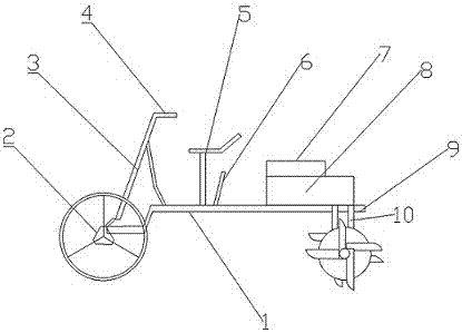
[0032] Such as figure 1 As shown, a micro tillage machine that is convenient for driving includes a micro tillage machine body 1, a front axle 2, a steering wheel 3, a seat 5, an engine 7, a gearbox 8 and a rear axle 9 are arranged on the micro tillage machine body 1, The front axle 2 is installed at the front end of the micro tillage machine body 1, and the front axle 2 is connected with the steering machine 3, a handle 4 is connected to the steering machine 3, a lever 6 is installed at the right rear of the seat 5, the engine 7 and Gear box 8 is installed on the rear of micro tiller body 1, and gear box 8 is installed on the micro tiller body 1, and engine 7 is installed on the top of box 8, and engine 7 is a water-cooled diesel engine, and the bottom of box 8 is connected with Two output shafts 10 are connected to the rear axle 9 .

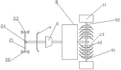
[0033] Such as figure 2As shown, the front axle 2 includes a crossbeam 21, a left bearing sleeve bar 22, a right bearing sleeve bar 23 and ...

Embodiment 2

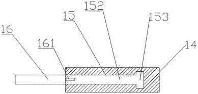
[0037] The difference from Example 1 is that, as Figure 6 As shown, an opening 111 is provided on the tire 11, and a sealing cover 112 used in conjunction with the opening 111 is arranged on the opening 111. The rotary tiller 12 includes a mounting seat 121 and a rotary tiller blade 122, and the rotary tiller blade 122 is made of high manganese and high carbon. Made of steel material. Such as Figure 7 As shown, the top of the second mounting rod 16 is provided with a U-shaped groove 162, and the tire 11 mounted on the second mounting rod 16 is a rubber tire.

[0038] When the tiller is going to cultivate the land, the sealing cover on the tire 11 is opened 112, all the gas inside the tire 11 is released, then the tire 11 is folded and placed in the U-shaped groove 162, and the second mounting rod 16 is placed along the Groove 151 advances in the first installation rod 14, then rotates the second installation rod 16, the second installation rod 16 and tire 11 are fixed in t...


PUM


Abstract

The invention belongs to the technical field of agricultural machinery, and discloses a mini-tiller easy to drive. The mini-tiller comprises a left drive rod, a right drive rod, a left bearing sleeve rod and a right bearing sleeve rod which each comprise a first installation rod and a second installation rod; the first installation rods are hinged with rotary blades, the second installation rods are provided with tyres, one end of each of the first installation rods of the left drive rod and the right drive rod is connected with an output shaft, and the other end is connected with the corresponding second installation rod in a sliding way; each of the ends, connected with the first installation rods, of the second installation rods is provided with a projection block of which the width is larger than the diameter of the corresponding second installation rod, each first installation rod is inside provided with a blind hole matched with the corresponding installation rod, the inner walls of two sides of each first installation rod are provided with two grooves between which the distance is the same as the width of the corresponding projection block; and each first installation rod is provided with a plurality of the rotary blades, elastic pieces are arranged between each first installation rod and the corresponding rotary blades, and the length of the rotary blades is larger than the diameter of the corresponding tyre. The mini-tiller solves the problems that the efficiency is not high and manual labor consumption is large in the prior art.

Description

technical field [0001] The invention belongs to the field of agricultural machinery, and in particular relates to a micro tillage machine which is easy to travel. Background technique [0002] In the cultivation of mountainous areas, hills or small fields, large-scale farming machinery is not suitable, so most of them use human or animal power, but this method has low efficiency, high labor intensity and low controllability of using animal power. In response to these defects, micro-tillage machines that can be cultivated in small fields, mountainous areas or hills have now appeared. [0003] Micro tillage machine refers to a small agricultural machine powered by diesel engine or gasoline engine, which has the characteristics of light weight, small size and simple structure. Tillers are widely used in plains, mountains, hills and other places. Tillers can travel freely in the field, and are convenient for users to apply and store, and can enter mountainous fields, so they a...

Claims


Application Information

Patent Timeline
Patent Type & Authority Applications(China)
IPC IPC(8): A01B33/08A01B33/14
CPCA01B33/08A01B33/144
Inventor 王科
Owner 重庆毓堡农业开发有限责任公司
Why Eureka
Try Eureka