
Novel electric stirring machine

An electric mixer, a new type of technology, applied in the direction of mixer accessories, mixers with rotating stirring devices, mixers, etc., can solve the problems of uneven additive addition effect, unsatisfactory mixing effect of additives and raw materials, etc., to achieve mixing effect Ideal, evenly added effect

Inactive Publication Date: 2017-08-29
张志通
View PDF3 Cites 7 Cited by
  • Summary
  • Abstract
  • Description
  • Claims
  • Application Information

AI Technical Summary

Problems solved by technology

[0002] In the chemical industry, the chemical reaction between some solvent substances generally needs to be mixed and put into the mixer for full mixing and stirring, so as to speed up the complete reaction. In the existing mixer, including the power control box, The top air hole and the discharge valve, the control panel is fixedly installed inside the power control box, and the power control box is fixed on one side of the support beam, the top air hole is fixed on the top of the main body of the mixer, and the bottom of the main body of the mixer is fixed. There are cooling holes at the bottom, the stirring blade is rotated by the rotating shaft, and the rotating shaft and the gear box are connected by a rotating motor. Although the heating device can be properly dissipated, the effect of adding solvent additives is not uniform in actual use, resulting in The mixing effect of additives and raw materials is not ideal

Method used


Image

  • Novel electric stirring machine
  • Novel electric stirring machine
  • Novel electric stirring machine

Examples


Embodiment 1

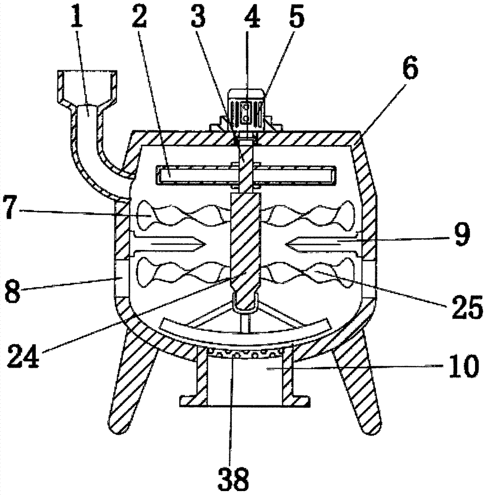
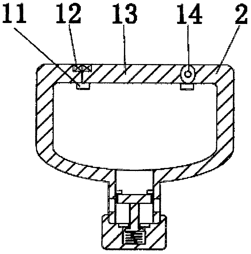
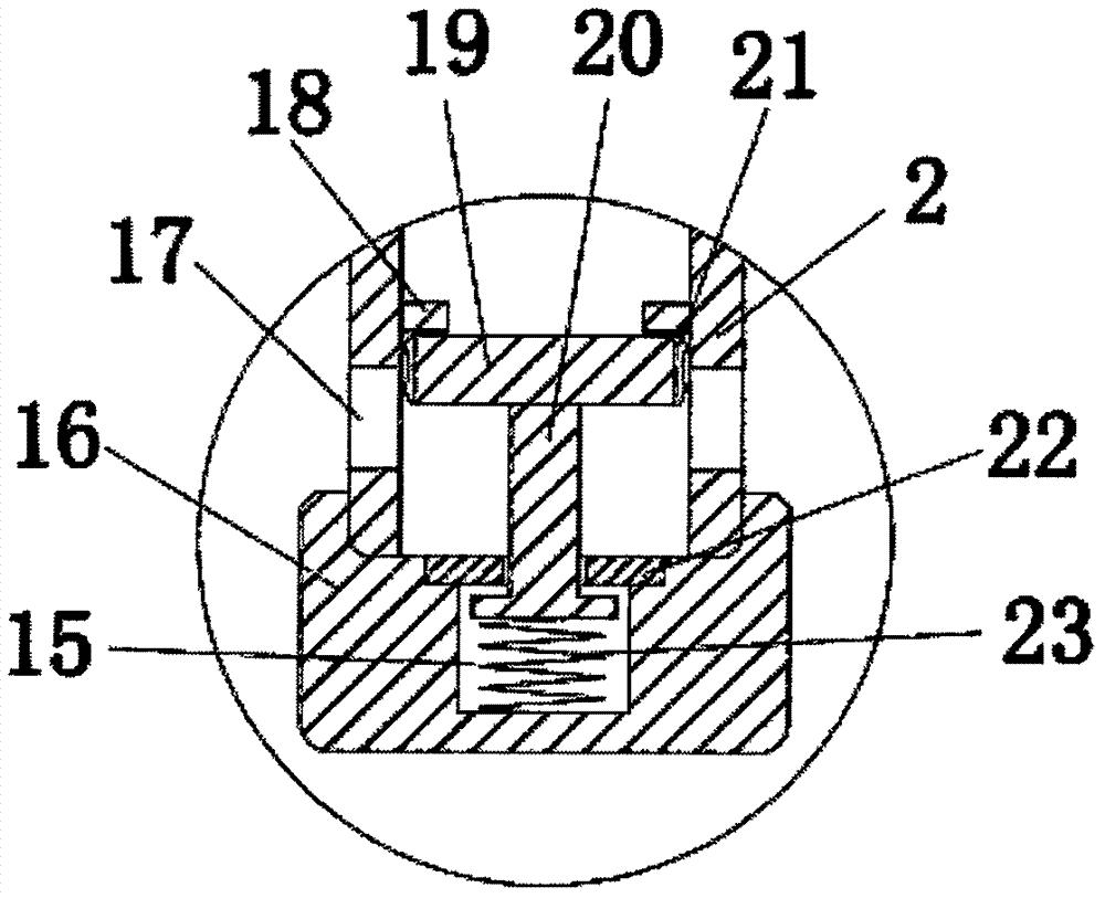
[0016] Example 1: Please refer to Figure 1-5 , the present invention provides a technical solution: a new type electric mixer, including a casing 6, the left top and bottom center of the casing 6 are respectively provided with a hopper 1 and a discharge hopper 10, the top center of the casing 6 A servo motor 5 is installed, the model of the servo motor 5 is MR-J2S-10A, and it is connected with an external power supply, the external power supply is 380V AC, the servo motor 5 works when the external power supply of the servo motor 5 is connected, and the external power supply of the servo motor 5 is disconnected. The power supply servo motor 5 stops working, the inner top of the casing 6 is provided with a rotating rod 3, the rotating rod 3 is connected with the servo motor 5 through a coupling 4, the bottom end of the rotating rod 3 is equipped with a stirring roller 24, and the outer side of the stirring roller 24 The first stirring blade 7 and the second stirring blade 25 ar...


PUM


Abstract

The invention discloses a novel electric stirring machine, which includes a machine shell. A material feeding hopper and a material discharging hopper are respectively arranged on the top end of the left side and the center of the bottom end of the machine shell. A material storage box is installed on the outer side of a rotary rod. A cover plate is disposed on the top end of the material storage box. A through hole is formed in the outer side of the bottom of the material storage box. A plugging plate is mounted on the top of an inner rod and is matched with an inner annular plate. Through combination of the material storage box, the plugging plate and stirring blades, the novel electric stirring machine stirs materials when a stirring roller rotates and drives the stirring blades to rotate, and when the rotary rod rotates, the material storage box is rotated, so that centrifugal force is generated by the material storage box, and the plugging plate, under effects of the centrifugal force, drives the inner rod to move outwardly to compress a compressive spring in a chamber, so that the materials are thrown into the machine shell through the through hole. The machine can uniformly spray an additive into the machine shell when the materials are stirred, so that the machine achieves auto-addition of the additive and has ideal mixing and stirring effects on the additive and the raw materials.

Description

technical field [0001] The invention relates to the technical field of machinery, in particular to a novel electric mixer. Background technique [0002] In the chemical industry, the chemical reaction between some solvent substances generally needs to be mixed and put into the mixer for full mixing and stirring, so as to speed up the complete reaction. In the existing mixer, including the power control box, The top air hole and the discharge valve, the control panel is fixedly installed inside the power control box, and the power control box is fixed on one side of the support beam, the top air hole is fixed on the top of the mixer main body, and the bottom of the mixer main body is fixed. There are cooling holes at the bottom, the stirring blade is rotated by the rotating shaft, and the rotating shaft and the gear box are connected by a rotating motor. Although the heating device can be properly dissipated, the effect of adding solvent additives is not uniform in actual use...

Claims


Application Information

Patent Timeline
IPC IPC(8): B01F15/06B01F15/02B01F15/00B01F7/18B01F7/00
CPCB01F27/092B01F27/074B01F27/90B01F35/3204B01F35/7171B01F35/71725B01F35/71805B01F35/90B01F2035/98B01F2101/2204
Inventor 张志通
Owner 张志通
Learn More