Anti-collision energy-absorbing structure of automobile and its manufacturing process

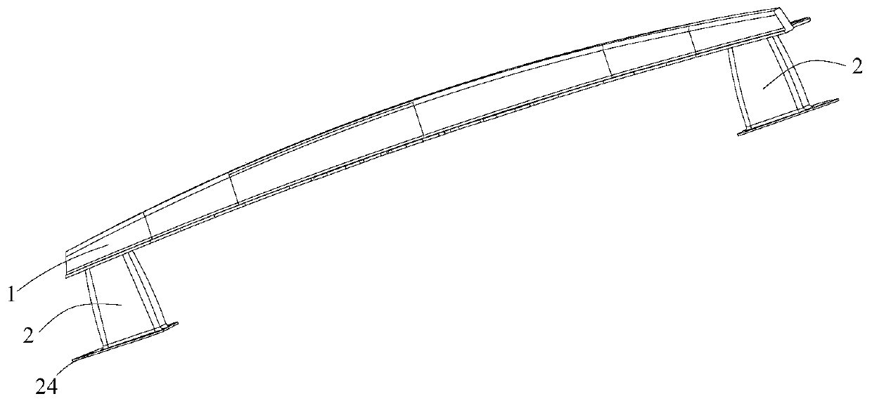
An energy-absorbing structure and anti-collision technology, which is applied to vehicle components, vehicle safety arrangements, bumpers, etc., can solve the problems of poor energy-absorbing effect of anti-collision beams and energy-absorbing boxes, and the structure of anti-collision beams is cumbersome. The effect of good impact energy absorption, strong surface strength and strong anti-collision energy absorption ability

Active Publication Date: 2020-01-31
SHENZHEN YATAIXING IND
View PDF7 Cites 0 Cited by
  • Summary
  • Abstract
  • Description
  • Claims
  • Application Information

AI Technical Summary

Problems solved by technology

[0003] The purpose of the present invention is to provide an automobile anti-collision energy-absorbing structure and its manufacturing process to solve the problem that the anti-collision beam and the energy-absorbing box are connected by bolts in the prior art and the anti-collision beam is made of metal materials, resulting in the anti-collision Technical problems of bulky beam structure and poor energy absorption effect of anti-collision beams and energy-absorbing boxes

Method used


Image

  • Anti-collision energy-absorbing structure of automobile and its manufacturing process
  • Anti-collision energy-absorbing structure of automobile and its manufacturing process
  • Anti-collision energy-absorbing structure of automobile and its manufacturing process

Examples


Embodiment Construction

[0025] In order to make the technical problems, technical solutions and beneficial effects to be solved by the present invention clearer, the present invention will be further described in detail below in conjunction with the accompanying drawings and embodiments. It should be understood that the specific embodiments described here are only used to explain the present invention, not to limit the present invention.

[0026] It should be noted that when an element is referred to as being “fixed” or “disposed on” another element, it may be directly on the other element or be indirectly on the other element. When an element is referred to as being "connected to" another element, it can be directly connected to the other element or indirectly connected to the other element.

[0027] It should be understood that the orientation or positional relationship indicated by the terms "length", "width", "front", "rear", "left", "right", "inner", "outer" etc. are based on the The orientatio...


PUM


Abstract

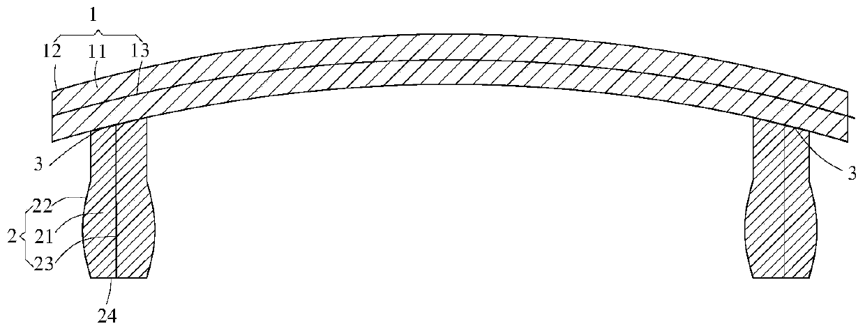
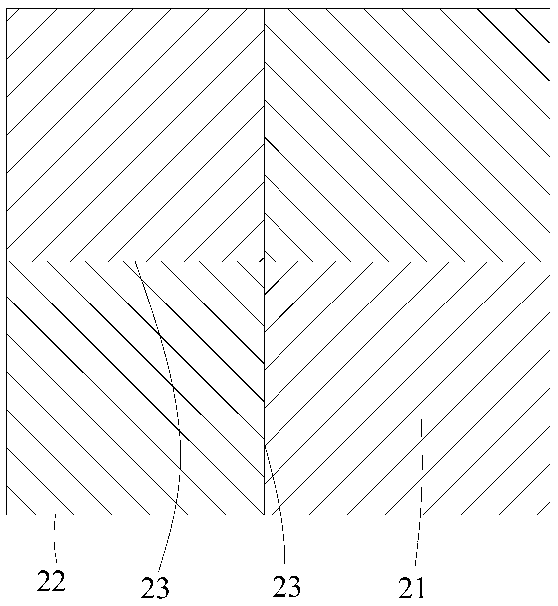
An automobile collision prevention and energy absorption structure, comprising a collision prevention portion (1) and energy absorption portions (2) provided at the two ends of the collision prevention portion (1); the collision prevention portion (1) comprises a collision prevention sandwich (11) and a multilayer collision prevention reinforcement layer (12) laid on the surface of the collision prevention sandwich (11), and each of the energy absorption portions (2) comprises an energy absorption sandwich (21) and a multilayer energy absorption reinforcement layer (22) laid on the surface of the energy absorption sandwich (21), the collision prevention reinforcement layer (12) and the two energy absorption reinforcement layers (22) being connected into an integral structure. A manufacturing process for an automobile collision prevention and energy absorption structure, comprising the following steps: S1: manufacturing the collision prevention sandwich (11) and the two energy absorption sandwiches (21) with foam, respectively; S3: combining the collision prevention sandwich (11) and the energy absorption sandwiches (21) into a whole, and laying a surface reinforcement layer made of multilayer fiber materials on the surface thereof; and S4, performing epoxy glue injection molding treatment on the surface reinforcement layer. The present structure is not only light in weight, but also good in collision prevention and energy absorption effects.

Description

technical field [0001] The invention belongs to the technical field of automobile component structures, and more specifically relates to an automobile anti-collision energy-absorbing structure and a manufacturing process thereof. Background technique [0002] With the growth of car ownership, safe travel has attracted widespread attention. In order to improve the safety performance of automobile collisions, anti-collision beams and energy-absorbing boxes are generally installed on the front longitudinal beams at the front of the car. In this way, during a car collision, the anti-collision beams and energy-absorbing boxes can improve the energy absorption effect of the car thereby slowing the impact. At present, the anti-collision beams and energy-absorbing boxes on the market are generally connected by bolts, and the anti-collision beams are made of metal materials such as steel and iron. The energy-absorbing effect of the energy-absorbing box is not good. Contents of th...

Claims


Application Information

Patent Timeline
Patent Type & Authority Patents(China)
IPC IPC(8): B60R19/22B60R19/30
CPCB60R19/023B60R19/22B60R19/30B60R2019/026B60R2019/247
Inventor 常健飞
Owner SHENZHEN YATAIXING IND
Why Eureka
Try Eureka