Outer cylinder cover and washing machine
A technology for an outer tub cover and a washing machine, which is applied in the field of washing machines, can solve the problems that the washing effect of clothes cannot be substantially improved, the spray effect cannot be achieved, the spray coverage area is small, etc., and the spray water flow is uniform and reliable, and the clothes wash The net effect is guaranteed and the effect of improving the cleaning rate
- Summary
- Abstract
- Description
- Claims
- Application Information
AI Technical Summary
Problems solved by technology
Method used
Image

Examples
Embodiment 1
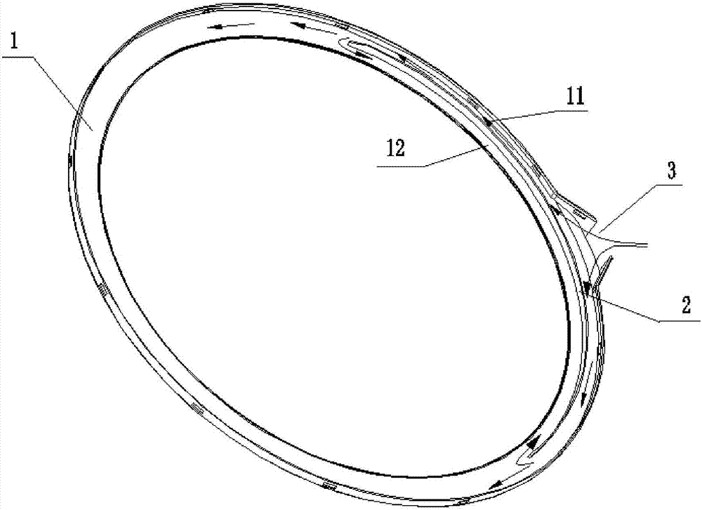
[0048] An outer bucket cover, comprising an upper cover body 101 and a lower cover body 102, the upper cover body 101 and the lower cover body 102 are connected to form a water cavity 1, the inner peripheral wall of the water cavity 1 is provided with a plurality of water outlets, the water cavity 1 is connected to the The connecting part of the water inlet 3 is provided with a water uniform rib 2 extending along the circumference of the outer barrel cover 100. The water inlet is blocked by the water uniform rib 2 to divert to the water chamber 1 on both sides of the water inlet 3 and sprayed evenly by each water outlet. to the inner barrel.
[0049] A first water cavity 11 is formed between the water uniform rib 2 and the outer peripheral wall of the outer bucket cover 100, and the first water cavity 11 communicates with the water inlet 3; a second water cavity is formed between the water uniform rib 2 and the inner peripheral wall of the outer bucket cover 100 Cavity 12.
...
Embodiment 2
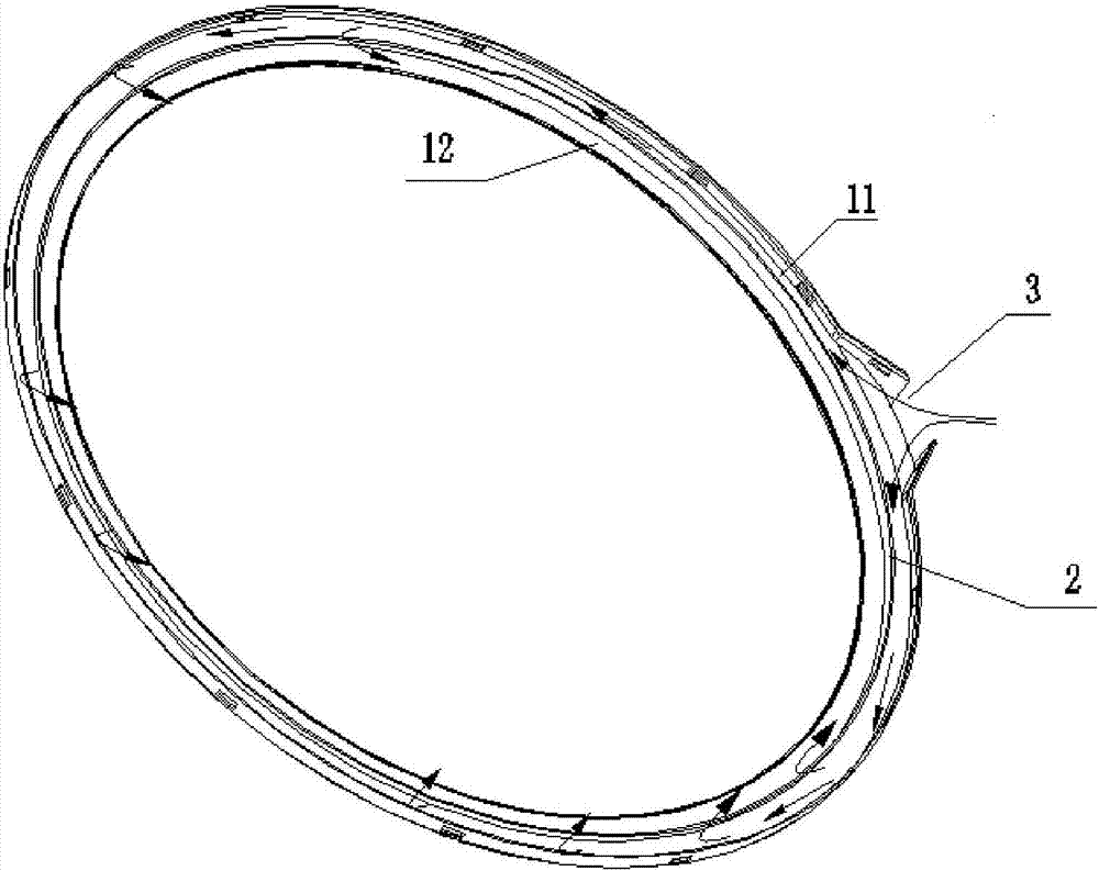
[0077] refer to image 3 , The difference between this embodiment and Embodiment 1 is that: the end points of the left and right sections of the ribs of the uniform water rib 2 are connected to form a full circle of ribs.
[0078] The uniform water rib 2 is arranged as a full circle in the water chamber 1. Those skilled in the art should know that the height of the part connecting the left and right section rib end points in the whole circle of ribs should satisfy: the water can enter through the first water chamber 11. to the second water chamber 12 so that the incoming water is sprayed out from the water outlet on the inner peripheral wall of the outer barrel cover 100 . see image 3 , the arrows in the figure indicate the flow direction of the water flow.
[0079] An outer bucket cover, comprising an upper cover body 101 and a lower cover body 102, the upper cover body 101 and the lower cover body 102 are connected to form a water cavity 1, the inner peripheral wall of th...
Embodiment 3
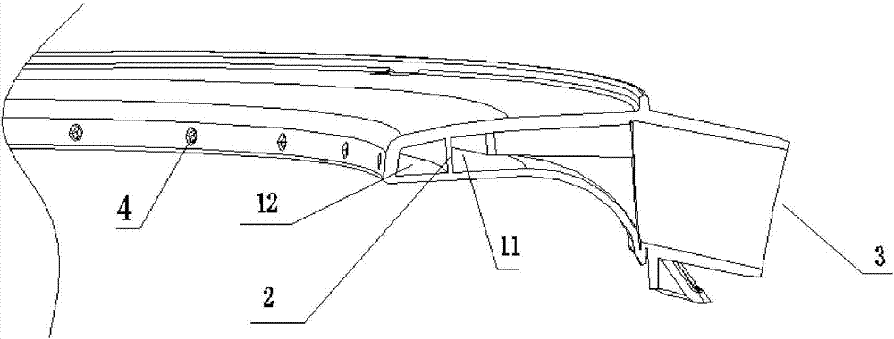
[0106] A novel water flow outer barrel cover, the outer barrel cover 100 includes an upper cover body 101 and a lower cover body 102 (such as Figure 4 As shown), the upper cover 101 and the lower cover 102 are provided with matching engaging parts, so that the upper cover 101 and the lower cover 102 engage and form a ring-shaped water cavity 1, the inner peripheral wall of the water cavity 1 There are a plurality of water outlet holes 4 on the top, and the outer barrel cover 100 is provided with a water inlet 3; water enters the annular water cavity 1 through the water inlet 3 and sprays into the inner barrel through the water outlet holes 4.
[0107] Each water outlet hole 4 is independently and evenly distributed on the inner peripheral wall of the water chamber 1;
[0108] Alternatively, the water outlet holes 4 are set as a plurality of water outlet hole groups 400 evenly distributed on the inner peripheral wall of the water chamber 1, and each water outlet hole group 400...
PUM
 Abstract
Description
Claims
Application Information
 - R&D
- Intellectual Property
- Life Sciences
- Materials
- Tech Scout
- Unparalleled Data Quality
- Higher Quality Content
- 60% Fewer Hallucinations
Browse by: Latest US Patents, China's latest patents, Technical Efficacy Thesaurus, Application Domain, Technology Topic, Popular Technical Reports.
© 2025 PatSnap. All rights reserved.Legal|Privacy policy|Modern Slavery Act Transparency Statement|Sitemap|About US| Contact US: help@patsnap.com