Vice-driving lubricating structure of sliding valve of railway brake valve with automatic switching action

A technology of automatic switching and lubricating mechanism, applied in the direction of sliding valve, valve shell structure, engine components, etc., can solve the problems of loss, failure to extend the life time of the sliding valve pair oil film, and reduce oil consumption. The effect of easy transformation of existing products and easy processing of new products

Pending Publication Date: 2017-08-29
MEISHAN CRRC BRAKE SCI & TECH CO LTD
View PDF8 Cites 2 Cited by
  • Summary
  • Abstract
  • Description
  • Claims
  • Application Information

AI Technical Summary

Problems solved by technology

[0003] However, in the actual application process, we found that the oil outlet groove on the throttle valve and the oil inlet port on the slide valve in the above structure are always in a communication state during the action cycle of railway brake valve charging, braking, pressure maintaining, and charging. , when the working surface of the throttle valve and the slide valve is scratched to varying degrees, the lubricating oil in the oil storage chamber will be quickly lost through the scratched throttle valve and the working surface of the slide valve under the action of the pressure air in the oil storage chamber , but the purpose of prolonging the existence time of the oil film of the spool valve pair and the service life of the spool valve pair cannot be achieved

Method used


Image

  • Vice-driving lubricating structure of sliding valve of railway brake valve with automatic switching action

Examples


Embodiment Construction

[0011] Below in conjunction with accompanying drawing, the present invention is described in detail.

[0012] In order to make the object, technical solution and advantages of the present invention clearer, the present invention will be further described in detail below in conjunction with the accompanying drawings and embodiments. It should be understood that the specific embodiments described here are only used to explain the present invention, not to limit the present invention.

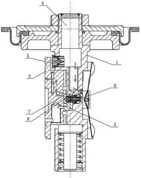
[0013] Such as figure 1 As shown, an active lubricating mechanism for railway brake valve slide valve pair with automatic switching function, including a main piston rod 1, a slide valve 2 and a throttle valve 3, an oil storage chamber 4 is arranged in the main piston rod 1, A one-way valve composition 5 is arranged on the main piston rod 1, and the oil storage chamber 4 communicates with the oil outlet 8 provided in the non-working area of ​​the working surface of the throttle valve 3 through th...


PUM


Abstract

The invention discloses a vice-driving lubricating structure of a sliding valve of a railway brake valve with automatic switching action. The vice-driving lubricating structure of the sliding valve of the railway brake valve with the automatic switching action comprises a main piston rod, a sliding valve and a graduating valve. An oil storage cavity is arranged in the main piston rod. A one-way valve assembly is arranged on the main piston rod. The oil storage cavity communicates with an oil outlet through an oil-way pipe, wherein the oil outlet is arranged at the non-working area of the working surface on the graduating valve. An oil inlet is arranged at the non-working area of the working surface of the sliding valve. The oil outlet of the graduating valve and the oil inlet of the sliding valve are not be communicated during an air inflation position and a pressure maintaining position in the cycle of motion of the railway brake valve, wherein the air inflation position and the pressure maintaining position occupy most of the time, while in the process of braking of the railway brake valve, the oil outlet of the graduating valve is instantly communicated with the oil inlet of the sliding valve, and the rest traveling all be closed. In this way, just as an automatic switch is arranged at the oil outlet of the graduating valve and the oil inlet of the sliding valve, the oil consumption of lubricating oil in the oil storage can be reduced greatly, and the existing time of a vice oil slick of the sliding valve and the vice service life of the sliding valve are prolonged remarkably.

Description

technical field [0001] The invention mainly relates to an active lubricating mechanism for a slide valve pair of a railway brake valve with an automatic switch function. Background technique [0002] Existing brake valves for railway vehicles have phenomena such as peeling off of the slide valve pair, pitting corrosion, and even leakage caused by poor lubrication during use, which seriously affects the performance stability of the brake valve. In order to overcome the above technical problems, an air control valve with an active lubrication structure is disclosed in the prior art (Patent No. 2015 2 0916572.4), which specifically discloses that it includes a main piston rod, a spool valve, a spool valve sleeve and a throttle valve. The main piston rod is provided with an oil storage chamber, and lubricating oil is stored in the oil storage chamber, and the chamber above the lubricating oil liquid level in the oil storage chamber is formed by a one-way valve arranged on the ma...

Claims


Application Information

Patent Timeline
Patent Type & Authority Applications(China)
IPC IPC(8): F16K3/30F16K27/04
CPCF16K3/30F16K27/04
Inventor 朱迎春王兴华李谋逵袁德强吕超安鸿肖维远杨建平
Owner MEISHAN CRRC BRAKE SCI & TECH CO LTD
Why Eureka
Try Eureka