
Novel three-step lens-free coherent diffractive imaging method

A technology of coherent diffraction imaging and coherent diffraction, which is applied in the field of new three-step lensless coherent diffraction imaging, can solve the problems of low sampling pattern accuracy, long experimental operation cycle, and poor imaging timeliness, and achieve convergence speed and accuracy improvement, The effect of improving efficiency and reducing random error

Active Publication Date: 2017-08-29
XIJING UNIV
View PDF7 Cites 4 Cited by
  • Summary
  • Abstract
  • Description
  • Claims
  • Application Information

AI Technical Summary

Problems solved by technology

See (Opt.Lett.30 (8), 833-5 (2005)) but on these technical schemes, they have following technical defect: need to obtain the diffraction surface of a plurality of different distances, take moving sample or CCD in the implementation process This method needs to change the position of the sample or CCD repeatedly, which requires a lot of repetitive work. At the same time, it introduces random errors that directly affect the experimental results. The accuracy of the obtained sampling pattern is not high, and requires Oversampling, long experimental operation cycle and weak operability, poor timeliness of imaging

Method used


Image

  • Novel three-step lens-free coherent diffractive imaging method
  • Novel three-step lens-free coherent diffractive imaging method
  • Novel three-step lens-free coherent diffractive imaging method

Examples


Embodiment 1

[0061] The imaging effect of the pure amplitude sample is as follows Figure 6 as shown, Figure 6 In the series of figures, 6a is the pure amplitude pattern to be measured, 6b is the diffraction pattern on the first diffraction plane at a distance of 300mm from the sample, 6c is the diffraction pattern on the second diffraction plane 50mm away from the first diffraction plane, and 6d is The diffraction pattern on the third diffraction plane at a distance of 50 mm from the second diffraction plane, 6e is the recovery result of 100 iterations of the three-step diffraction iterative algorithm. The correlation coefficient of 6a and 6e is 0.9991, indicating that this method can achieve good imaging results for pure amplitude objects.

Embodiment 2

[0063] The imaging effect of complex amplitude samples is as follows Figure 7 as shown, Figure 7 In the series of figures, 7a is the amplitude part of the restored amplitude type object, 7b is the phase part of the restored amplitude type object, 7c is the diffraction pattern on the first diffraction plane at a distance of 300mm from the object, and 7d is 50mm away from the first diffraction plane The diffraction pattern on the second diffraction plane at , 7e is the diffraction pattern on the third diffraction plane at a distance of 50mm from the second diffraction plane, 7f and 7g are the amplitude part and phase part reconstructed by the three-step coherent diffraction algorithm iteration 100 times, respectively. The correlation coefficient of 7a and 7f is 0.9982, and the correlation coefficient of 7b and 7g is 0.9763. It shows that this method can achieve good imaging effect on complex amplitude objects.


PUM


Abstract

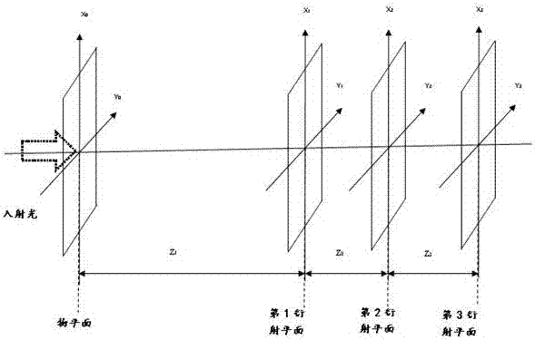
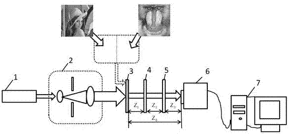
The invention relates to a novel three-step lens-free coherent diffractive imaging method. The method is characterized in that laser beams subjected to collimation and beam expansion are used to illuminate a to-be-measured sample, and recording a diffraction pattern when the front end of CCD has no optical parallels, a diffraction pattern when the front end of the CCD has one optical parallel and a diffraction pattern when the front end of the CCD has two optical parallels; using an algorithm combining wave filtering and coherent diffractive imaging to process the three diffraction patterns, and rebuilding the complex amplitude image of the to-be-measured sample. The novel three-step lens-free coherent diffractive imaging method has the advantages that the bottleneck problem that a traditional coherent diffractive imaging method needs to move the CCD or the to-be-measured sample for multiple times is solved effectively, the problems of random errors during moving and experiment operability are solved at the same time, the method is simple and fast in experiment operation and high in operability, the coherent diffractive imaging algorithm is effectively combined with wave filtering, and convergence rate and a sample recovery effect are increased.

Description

technical field [0001] The invention relates to the technical field of optical diffraction imaging, in particular to a novel three-step lensless coherent diffraction imaging method. Background technique [0002] There have been many developments in lensless coherent diffraction imaging in recent years, and the method generally uses an iterative algorithm. The complex amplitude information of the object can be reproduced from the diffraction intensity pattern of the object without reference light. It has a very wide range of wavelengths and has been widely used in lensless coherent diffraction imaging of X-rays and electron beams. See (Opt.Lett.31, 3095-3097 (2006); J.Opt.Soc.Am.A25, 416-422 (2008); Nat.Phys., 4, 394-398 (2008); Appl.Opt. 21, 2758-2769 (1982); J.Opt.Soc.Am.A 23, 1179-1200 (2006)) After the sample is irradiated by a beam of coherent light, the diffraction pattern generated by the sample is received on the CCD. In order to obtain more accurate amplitude and p...

Claims


Application Information

Patent Timeline
IPC IPC(8): G01N21/47
CPCG01N21/4788
Inventor 李拓刘丹刘辉代饶张芝琳
Owner XIJING UNIV
Learn More