Spatial multichannel fiber coupler with laser induced synchronous fluorescence detection

A technology of laser-induced fluorescence and fiber-optic coupling devices, which is applied in the field of optics to achieve the effects of reducing costs, improving detection efficiency, and avoiding random errors

Inactive Publication Date: 2004-09-22
SHANGHAI JIAO TONG UNIV
View PDF0 Cites 3 Cited by
  • Summary
  • Abstract
  • Description
  • Claims
  • Application Information

AI Technical Summary

Problems solved by technology

[0003] The purpose of the present invention is to solve the problem of synchronous reference detection of fluorescent substances in dynamic processes such as biology, medicine and chemical reactions by providing a fiber coupling device for synchronous detection of spatial multi-channel laser-induced fluorescence. Detecting the fluorescence spectrum of the sample can also improve the detection accuracy and efficiency

Method used


Image

  • Spatial multichannel fiber coupler with laser induced synchronous fluorescence detection
  • Spatial multichannel fiber coupler with laser induced synchronous fluorescence detection
  • Spatial multichannel fiber coupler with laser induced synchronous fluorescence detection

Examples


Embodiment Construction

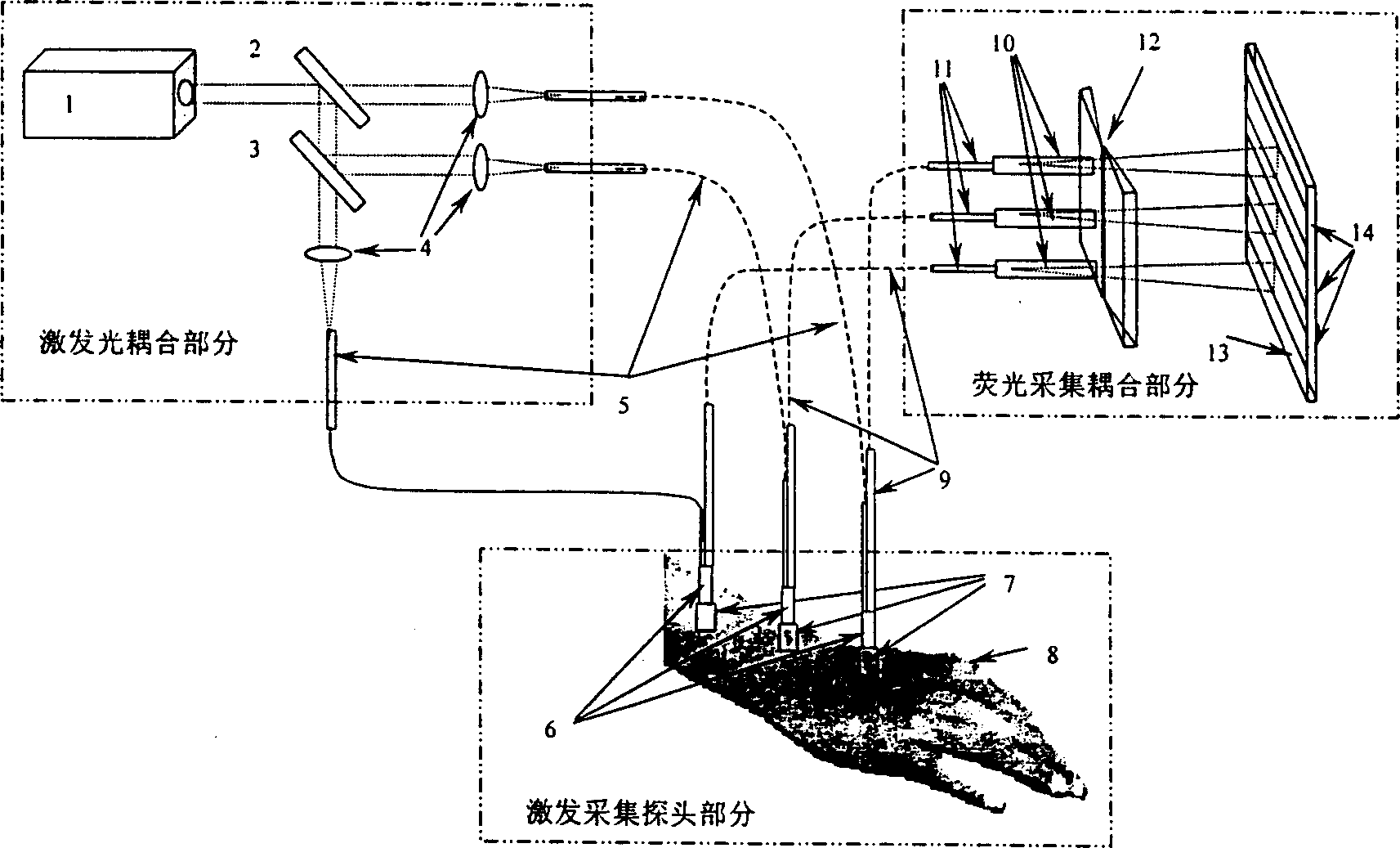
[0012] The technical solutions of the present invention will be further described below in conjunction with the accompanying drawings and specific embodiments.

[0013] Such as figure 1 As shown, the device of the present invention includes an excitation light coupling part, an excitation collection probe part and a fluorescence collection coupling part. The function of the excitation light coupling part is to generate three laser beams with equal optical power, and couple them into the excitation fiber respectively. The optical power of the laser beam output by laser 1 is P 0 , in the first beam splitter 2 (T 2 =33.3%), it is divided into two beams, the angle between the beam splitter plane and the laser beam is 45°, and the transmitted light power is P 0 / 3, the reflected beam is at the second beam splitter 3(T 3 =50%) were divided into two bundles. The optical powers of the three beams obtained by splitting the beams of the first beam splitter 2 and the second beam spl...


PUM


Abstract

A fiber coupler for synchronous test of spatial multi-channel aser adjust fluorescence inclues a laser beam coupled into an exciting fiber with equal power via a beam split mirror and a focussing lens. The output terminal of the exciting fiber is surrounded by exciting collect probes grouped by equal quantity of fluorescent collect fibers and housed with positioning liners. The fluorescent collect fibers in linear array are put in the liner diaphragm and aligned with the slit of spectrometer with a photoelectric transducer on its exit focus surface. This invention can guarantee the same test conditions for laser adjust fluorescent test spots with different spaces including same density of exciting light energy of the test spots, same fluorescent collect spatial angles and same fluorescent spectrom density with same samples.

Description

Technical field: [0001] The invention relates to an optical fiber coupling device, in particular to an optical fiber coupling device for synchronous detection of spatial multi-channel laser-induced fluorescence, which is used for simultaneous detection of laser-induced fluorescence spectra of different samples, and belongs to the field of optical technology. Background technique: [0002] At present, laser-induced fluorescence detection technology is widely used in substance detection and material component analysis, especially in biomedical diagnosis. Laser-induced fluorescence detection refers to: irradiating a material sample with a laser in the ultraviolet or visible light band, some material samples will emit fluorescent radiation with a wavelength greater than that of the incident laser, and its fluorescence spectrum characteristics reflect the energy level structure of the material, so it can be used as a material analysis the wrist of. In practical applications, it ...

Claims


Application Information

Patent Timeline
Patent Type & Authority Patents(China)
IPC IPC(8): A61B10/00G01J3/443G01N21/64G01N33/483G02B6/26G02B6/42
Inventor 于常青赵海鹰方为军窦晓鸣
Owner SHANGHAI JIAO TONG UNIV
Why Eureka
Try Eureka