Control device and system of circuit breaker

A control device and circuit breaker technology, applied in the direction of circuit devices, electrical components, emergency power protection, etc., to achieve continuous power supply and improve reliability

Pending Publication Date: 2017-08-29
QINGDAO TGOOD ELECTRIC +1
View PDF5 Cites 4 Cited by
  • Summary
  • Abstract
  • Description
  • Claims
  • Application Information

AI Technical Summary

Problems solved by technology

[0004] Based on the advantages of the permanent magnet mechanism, there is currently no reliable control device to continuously and effectively control it. Therefore, the development of a circuit breaker control device or system has important practical significance and application prospects

Method used


Image

  • Control device and system of circuit breaker
  • Control device and system of circuit breaker
  • Control device and system of circuit breaker

Examples


Embodiment 1

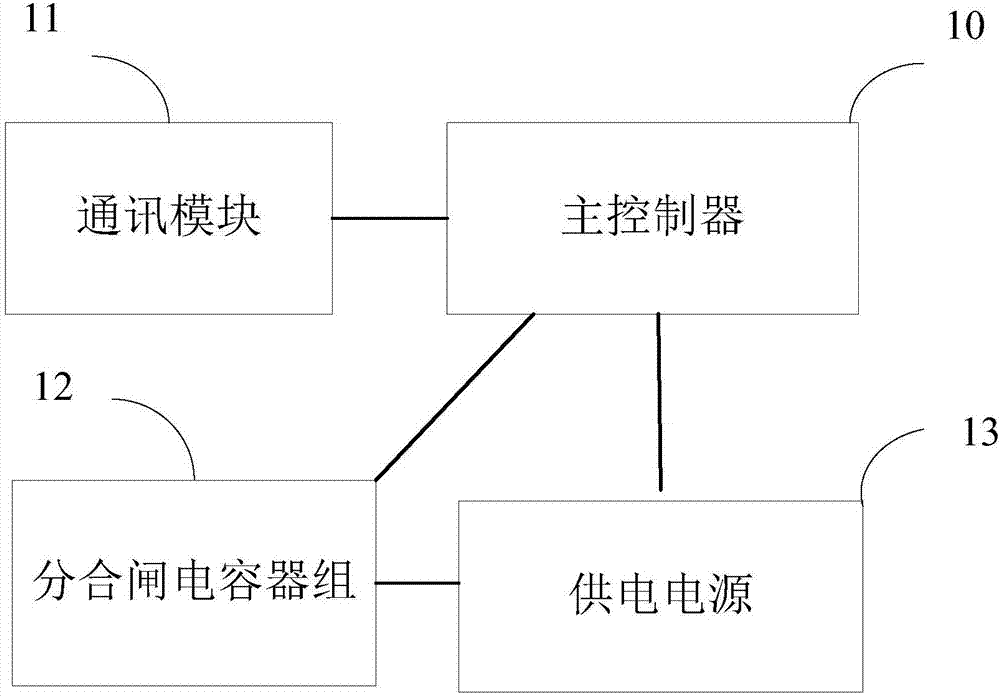
[0032] An embodiment of the present invention provides a control device for a circuit breaker, which can be applied to the field of control of circuit breakers including permanent magnet mechanisms. Such as figure 1 and figure 2 As shown, the control device includes: a main controller 10 , a communication module 11 , an opening and closing capacitor bank 12 and a power supply 13 .

[0033] Wherein, the communication module 11 , the opening and closing capacitor bank 12 and the power supply 13 are respectively connected to the main controller 10 , and the opening and closing capacitor bank 12 is connected to the power supply 13 .

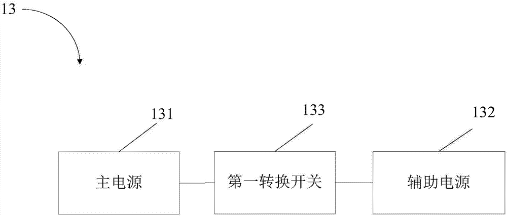
[0034] The power supply 13 includes a main power supply 131 and an auxiliary power supply 132 , a first transfer switch 133 is arranged between the main power supply 131 and the auxiliary power supply 132 , and the first transfer switch 133 is used for switching between the main power supply 131 and the auxiliary power supply 132 .

[0035] The fi...

Embodiment 2

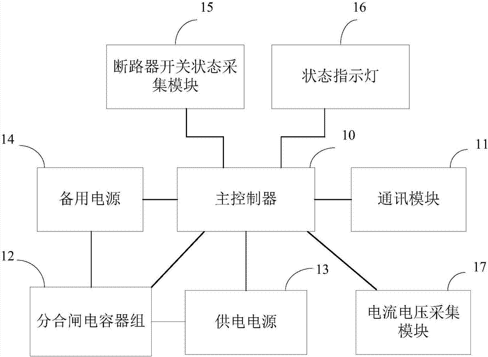
[0044] The embodiment of the present invention provides a circuit breaker control device, such as image 3 and Figure 4 As shown, the control device is based on the first embodiment. Specifically, in order to further ensure the safety of power supply, the control device also includes a backup power supply 14 . The backup power supply 14 is connected to the opening and closing capacitor bank 12 and the main controller 10 respectively. A power switching switch (not shown in the figure) is arranged between the backup power supply 14 and the power supply 13, and the power switching switch is used in an emergency (the power supply 13 is abnormal, such as when the driving current caused by the low power of the battery pack is insufficient), switching The backup power supply 14 supplies power to the control device (for example, mainly to the opening and closing capacitor bank 12 and the main controller 10).

[0045] Further, the backup power source 14 includes any one of a manual ...

Embodiment 3

[0056] Such as Figure 5 As shown, the embodiment of the present invention also provides a circuit breaker control system, which includes a host computer 500 and the control device 600 described in Embodiment 1 or Embodiment 2, and the host computer 500 is connected to the control device 600 by communication. Specifically, the upper computer 500 is connected to the control device 600 through a communication module.


PUM


Abstract

The invention provides a control device and system of a circuit breaker, and relates to the technical field of circuit breaker control. The control device and system can be used for achieving effective control on the circuit breaker and can also be used for achieving continuous power supply and improving the reliability. The control device comprises a master controller, a communication module, a breaking-closing capacitor bank and a power supply, wherein the communication module, the breaking-closing capacitor bank and the power supply are connected with the master controller, the breaking-closing capacitor bank is connected with the power supply, the power supply comprises a main power supply and an auxiliary power supply, a first conversion switch is arranged between the main power supply and the auxiliary power supply and is used for switching between the main power supply and the auxiliary power supply, and the auxiliary power supply comprises a storage battery pack.

Description

technical field [0001] The invention relates to the technical field of circuit breaker control, in particular to a circuit breaker control device and system. Background technique [0002] A circuit breaker is a current switching device that can open and close normal and abnormal circuits. It can be used to switch on and off load circuits, and can also be used to control motors that start infrequently. Circuit breakers have become indispensable and very important in distribution networks. Important protection electrical appliances. [0003] At present, traditional circuit breakers are mainly divided into permanent magnet circuit breakers and spring circuit breakers. Spring circuit breakers include spring operating mechanisms, which are mechanical systems composed of complex transmission mechanisms and require more mechanical parts. High cost and lack of reliability. Compared with spring circuit breakers, permanent magnet circuit breakers contain permanent magnet mechanisms,...

Claims


Application Information

Patent Timeline
Patent Type & Authority Applications(China)
IPC IPC(8): H02J13/00H02H1/06
CPCH02J13/0017H02H1/06
Inventor 屈东明汤川孙学锋王涛吕东飞刘文安冯忠奎周君李广智骆祥华王贵罡孙福鹏
Owner QINGDAO TGOOD ELECTRIC
Why Eureka
Try Eureka