Taper magnetic bearing switch reluctance motor and control method thereof

A technology of switched reluctance motor and reluctance motor, which is applied in the direction of AC motor control, control system, and mechanical energy control, etc. It can solve the problem of unbalanced levitation force, affecting the stability of levitation operation, high-speed levitation accuracy, and uneven output of radial levitation force. Balance and other issues

Active Publication Date: 2017-08-29
NANJING UNIV OF POSTS & TELECOMM
View PDF2 Cites 3 Cited by
  • Summary
  • Abstract
  • Description
  • Claims
  • Application Information

AI Technical Summary

Problems solved by technology

However, since the three-phase armature current takes turns as the current to generate the bias flux, due to the limitation of the E-type magnetic bearing stator, the bias flux generated when one phase is turned on is different from that of the other two phases, resulting in the output of the levitation motor The suspension force is not balanced, which affects the stability of suspension operation and high-speed suspension accuracy
Therefore, the present invention proposes a tapered magnetic bearing switched reluctance motor and its con

Method used


Image

  • Taper magnetic bearing switch reluctance motor and control method thereof
  • Taper magnetic bearing switch reluctance motor and control method thereof
  • Taper magnetic bearing switch reluctance motor and control method thereof

Examples


Embodiment Construction

[0068] The technical scheme of a tapered magnetic bearing switched reluctance motor and its control method of the present invention will be described in detail below in conjunction with the accompanying drawings:

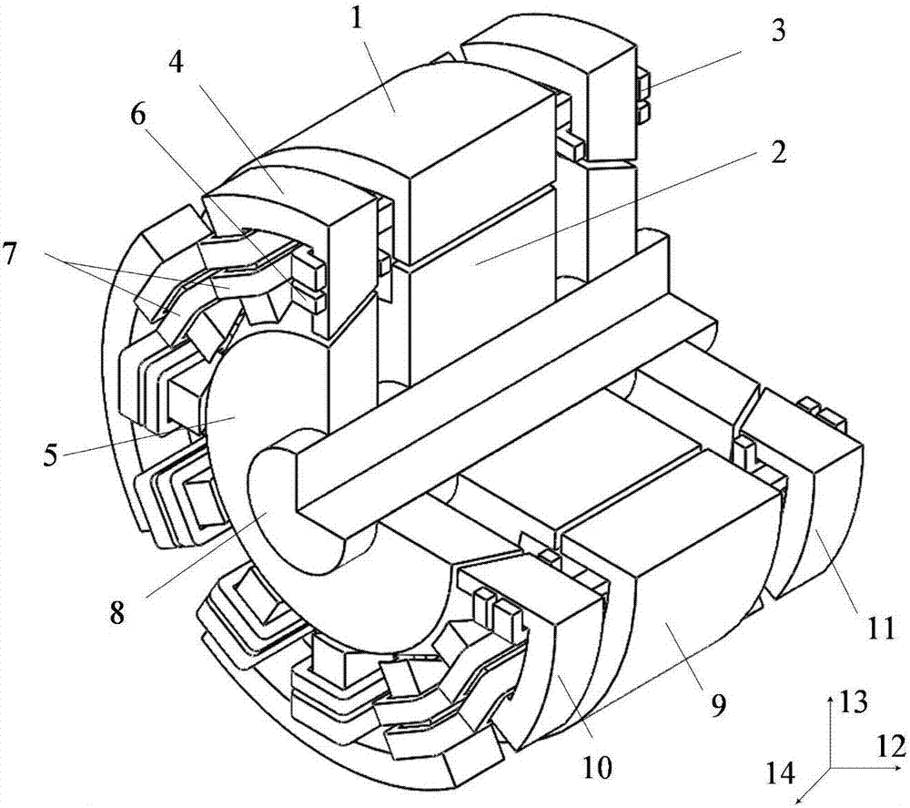
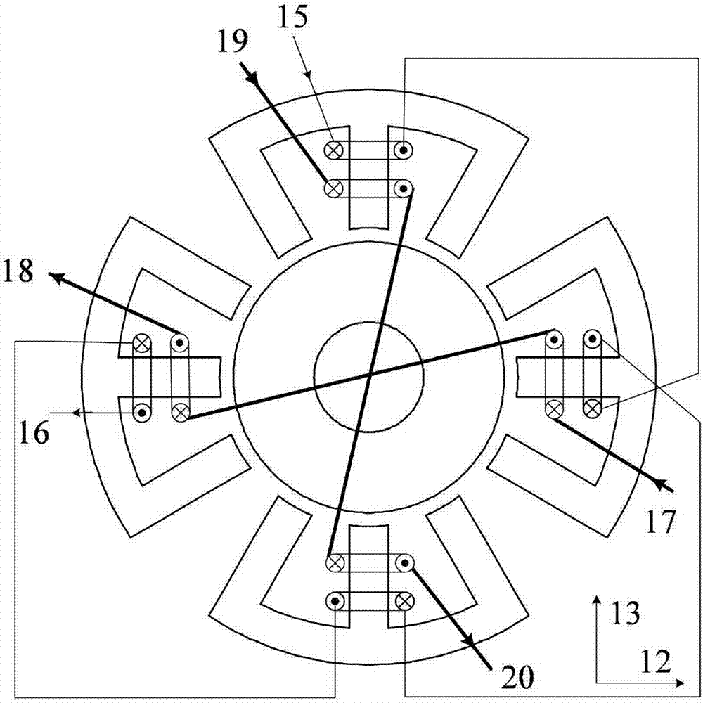
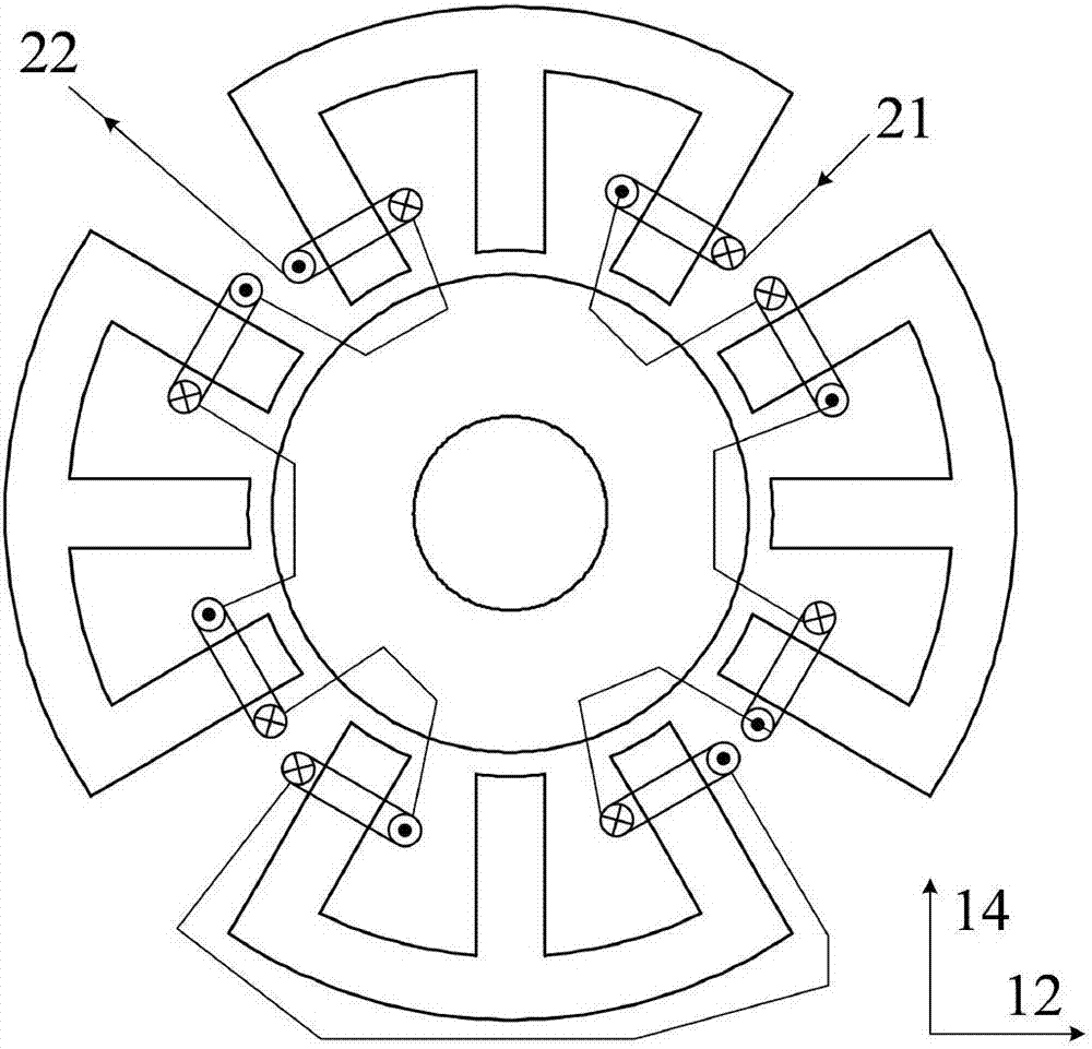
[0069] Such as figure 1 Shown is the three-dimensional structural schematic diagram of the tapered magnetic bearing switched reluctance motor of the present invention, wherein, 1 is the stator of the reluctance motor, 2 is the rotor of the reluctance motor, 3 is the armature winding, 4 is the tapered stator, and 5 is the cone 6 is the radial suspension winding, 7 is the axial suspension winding, 8 is the rotating shaft, 9 is the 12 / 8 pole switched reluctance motor, 10 is the tapered magnetic bearing I, 11 is the tapered magnetic bearing II, 12, 13 and 14 are the positive directions of the coordinate axes in the x, y and z directions respectively.

[0070] A tapered magnetic bearing switched reluctance motor, comprising a tapered magnetic bearing I, a switched reluc...


PUM


Abstract

The present invention discloses a taper magnetic bearing switch reluctance motor and a control method thereof. The motor is formed by one switch reluctance motor and two taper magnetic bearings; a taper stator is formed by 4 E-shaped structures, the central tooth of each E-shaped structure is winded with a vertical suspension winding, is winded at, each of other two teeth are respectively winded with an axial direction suspension winding, the vertical suspension windings and the axial direction suspension windings are connected in series to form a set of the axial direction suspension winding; an armature winding crosses the two taper stators and a reluctance motor stator to form 3-phase armature winding; rotation control is the same as a traditional switch reluctance motor control mode, and bias flux is generated for suspension; and five suspension forces are associated with the 3-phase armature winding current, current of 4 vertical suspension windings and current of 2 vertical suspension windings; the two vertical suspension windings can optimize the bias flux to allow the generated bias flux to be equal when the 3-phase armature winding performs individual excitation so as to solve the problem that the vertical suspension force output is unbalance. The motor system is high in integration degree and high in current utilization rate and realizes decoupling between the torque and the suspension force.

Description

technical field [0001] The invention relates to a tapered magnetic bearing switched reluctance motor and a control method thereof, belonging to the technical field of magnetic levitation switched reluctance motors and control thereof. Background technique [0002] The magnetic levitation switched reluctance motor not only has the advantages of no friction and no lubrication, but also inherits the high-speed adaptability of the switched reluctance motor and meets the harsh working environment. It has unique advantages in aerospace, flywheel energy storage and military applications. [0003] Tapered magnetic bearing switched reluctance motor is a new type of magnetic levitation motor, which can realize the natural decoupling of torque and levitation force, and utilizes the magnetic flux generated in the magnetic bearing by the armature winding current of the switched reluctance motor as The bias flux needed to generate the levitation force; in addition, since the magnetic bear...

Claims


Application Information

Patent Timeline
IPC IPC(8): H02K7/09H02K3/28H02N15/00H02P25/08
CPCH02K3/28H02K7/09H02K2213/03H02N15/00H02P25/08
Inventor 刘泽远蔡骏杨艳曹鑫邓智泉郭前岗
Owner NANJING UNIV OF POSTS & TELECOMM
Why Eureka
Try Eureka