Method of manufacturing concrete structural blocks for use in wind turbine towers

A technology of wind turbines and concrete structures, which is applied in the assembly of wind turbines, the configuration of installation/support of wind turbines, wind power generation, etc., and can solve the problems of complex implementation and long time consumption

Inactive Publication Date: 2020-06-16
SOLETANCHE FREYSSINET SAS
View PDF5 Cites 0 Cited by
  • Summary
  • Abstract
  • Description
  • Claims
  • Application Information

AI Technical Summary

Problems solved by technology

These steps are therefore time-consuming and complex to implement

Method used


Image

  • Method of manufacturing concrete structural blocks for use in wind turbine towers
  • Method of manufacturing concrete structural blocks for use in wind turbine towers
  • Method of manufacturing concrete structural blocks for use in wind turbine towers

Examples


Embodiment Construction

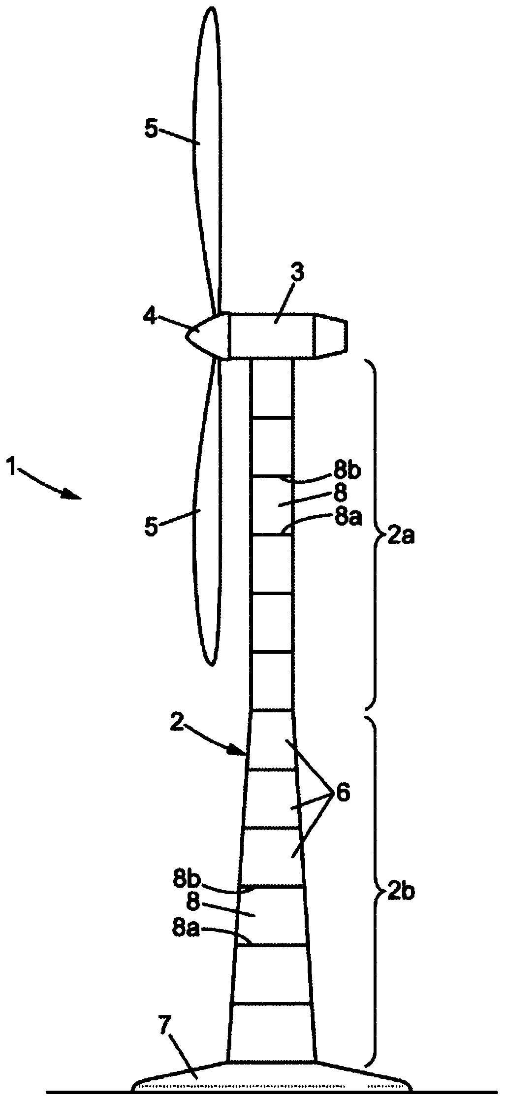
[0037] Such as figure 1 As shown, a wind turbine 1 comprises a tower 2 topped with a nacelle 3 and a rotor 4 comprising a plurality of blades 5 .

[0038] The tower 2 comprises a plurality of blocks 6 stacked on top of each other, thereby giving the tower 2 a generally elongated shape.

[0039] In the rest of the description, the tower 2 is considered to extend in a vertical direction.

[0040] The tower 2 is rigidly fixed to the foundation or foundation plate 7 .

[0041] The height of block 6 is preferably identical.

[0042] Each block 6 is constructed using a material such as reinforced concrete.

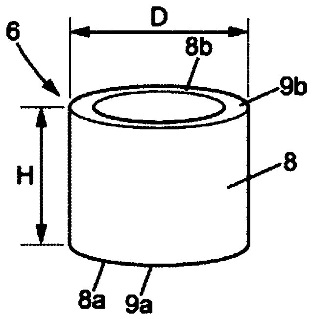
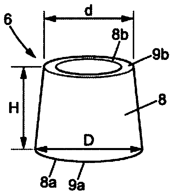
[0043] Such as figure 1 It can be seen that each block 6 of the upper part 2a is generally cylindrical, while each block 6 of the lower part 2b is generally conical.

[0044] Of course, the invention is not only applicable to the tower 2 shown, but may also be applicable to other tower forms, such as towers consisting only of cylindrical blocks or towers consisting only of ...


PUM


Abstract

The present invention relates to a method of manufacturing concrete structural blocks (6) for a wind turbine tower comprising at least two continuous blocks through the contact surface of each of the two blocks fixed to each other, the manufacturing method comprising the steps of: pouring concrete into a first reinforcement cage (10-1), thereby obtaining a first concrete structural block comprising an upper contact surface (9b); and pouring concrete into a second reinforcement cage In (10-2), the second concrete structural block is obtained, the second reinforcing cage is arranged in the formwork (21), and the formwork (21) is set so that the upper contact surface ( 9b) Forming a wall (26) delimiting the poured concrete so as to form the lower contact surface (9a) of the second block (6-2).

Description

technical field [0001] The invention relates to a method of manufacturing a concrete structural block for a wind turbine tower made of at least two continuous blocks. Background technique [0002] Typically, such a tower is topped with a nacelle and a rotor consisting of a plurality of blades in order to form a wind generator. [0003] Two consecutive blocks are stacked on top of each other by the contact surface of each of the two blocks. [0004] It is known to manufacture each block by assembling a plurality of panels at the installation site of the wind turbine or pouring concrete into a mould, for example a cylindrical mould. In this case, once the concrete has set, removal from the mold makes it possible to directly obtain the concrete structural block in one-piece form. [0005] Two consecutive blocks are secured by a concreted joint, or mortar or grout, depending on the thickness of the joint on the contact surface of each block. [0006] Due to imperfections or g...

Claims


Application Information

Patent Timeline
Patent Type & Authority Patents(China)
IPC IPC(8): B28B7/00B28B15/00B28B23/02E04H12/12E04H12/18E04H12/34F03D13/10F03D13/20
CPCB28B7/0088B28B15/00B28B23/02E04H12/12E04H12/185E04H12/342F05B2230/60F05B2240/912F03D13/10F03D13/20F05B2230/20F03D13/22Y02E10/72Y02E10/728Y02P70/50B28B17/0063E04C5/0622E04G11/062
Inventor 尼库拉斯·法布里伯诺伊特·梅伦埃里克·梅利厄
Owner SOLETANCHE FREYSSINET SAS
Why Eureka
Try Eureka