Supercharge Your Innovation With Domain-Expert AI Agents!

Plasma exhaust gas purification

A plasma and plasma source technology, applied in the field of plasma exhaust gas purification, can solve problems such as viscous failure, and achieve the effect of increasing service life and improving economy

Active Publication Date: 2020-12-04
BRUECKNER MASCHB
View PDF16 Cites 0 Cited by
  • Summary
  • Abstract
  • Description
  • Claims
  • Application Information

AI Technical Summary

Problems solved by technology

Dust-like deposits occur in the particulate filter, which can sometimes fail viscously

Method used


Image

  • Plasma exhaust gas purification
  • Plasma exhaust gas purification
  • Plasma exhaust gas purification

Examples


Embodiment Construction

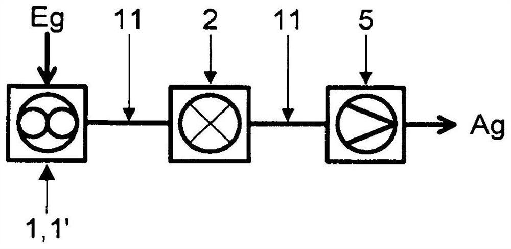
[0090] The following reference figure 1 The basic principle of the present invention is further explained.

[0091] here figure 1 A plasticizing unit 1, for example in the form of an extruder or, for example, in the form of a twin extruder 1.1', a plasma source 2 connected downstream and a further vacuum device 5 connected downstream of the plasma source 2 are shown in the schematic diagram, The vacuum system is also partly referred to as vacuum system 5 . The whole arrangement is interconnected by conduits 11 (pipes).

[0092] thus, figure 1 Again, the simplest conceivable configuration of the arrangement according to the invention is given, in which the mentioned plasma source 2 is available directly after the extruder 1 , 1 ′ and any separation is made superfluous here.

[0093] according to figure 1 The corresponding plasticizing unit 1 of the first embodiment comprises, for example, an extruder 1 , 1 ′ which, as is known, generally has at least one or two (or more) p...


PUM


Abstract

The invention relates to an improved method for degassing polymer melts and for detoxification of hazardous substances produced therein and an improved method for degassing and detoxification of polymer melts The system of hazardous substances produced here is characterized by the following features: The hazardous substances are removed from the degassing zone (VD; VD1, VD2) and fed to the filter stage or separator (4; 4.1, 4.2) A plasma source (2; 2.1, 2.2, 2.3, 2.4) which is constructed and / or formed in such a way that in the plasma source (2; 2.1, 2.2, 2.3, 2.4) harmful substances are completely or partially converted into Plasma aggregation.

Description

technical field [0001] The invention relates to a method and a system for degassing a polymer melt and detoxifying the exhaust gases generated therein. Background technique [0002] Extruders are frequently used in the manufacture of polymer products in order to melt plastic pellets and (when required for the corresponding properties of the finished plastic product) incorporate one or more liquid or solid additives (e.g. softeners, lubricants) , antistatic agent, etc.) and delivered to the extrusion nozzle. The temperature of the melt is in the range between 200° C. and 300° C. here. [0003] The resulting polymer melt contains gaseous inclusions and liquid substances in solution in its interior after melting, which has an adverse effect on the quality of the finished product when the melt is processed in a mold. Inclusions are very disadvantageously detectable in the production of plastic films. In the plasticizing unit, therefore, the melting of the plastic and the mixi...

Claims


Application Information

Patent Timeline
Patent Type & Authority Patents(China)
IPC IPC(8): B29C48/14B29C48/76B29C48/92B29B7/84B29C48/40
CPCB29C48/767B29C48/92B29C48/145B29C2948/00B29C2948/92723B29C48/40B29B7/847B29B7/86B29B2013/005B29B13/00B29B7/46B29B7/72B29B7/82B29B7/84B01D53/323B01D53/54B01D53/944B01D2259/818F01N3/0275F01N2240/28
Inventor J·艾施N·安布罗修斯-福斯R·施武筹S·塞博尔
Owner BRUECKNER MASCHB
Features
  • R&D
  • Intellectual Property
  • Life Sciences
  • Materials
  • Tech Scout
  • Unparalleled Data Quality
  • Higher Quality Content
  • 60% Fewer Hallucinations
Learn More