Valve battery

A technology of batteries and safety valves, applied in valve details, valve devices, valve housing structures, etc., can solve the problem of no longer waiting

Active Publication Date: 2017-08-29
FESTO AG & CO KG
10 Cites 0 Cited by

AI-Extracted Technical Summary

Problems solved by technology

This creates the risk that the valve tappet is bent in this position by the action of an exter...

Abstract

The invention relates to a valve battery, comprising a plurality of, in particular, electrically actuatable control valves (15), each of which is connected simultaneously to at least one common feed channel (21) and at least one common ventilation channel (22, 23) by means of at least one individual supply channel (33) in order to be able to control the connection of these channels with at least one respective individual working channel (24, 25) that can be connected to a consumer, wherein a safety valve device (29), which is switched into the at least one individual supply channel (33), is provided with at least one safety valve (30) which is switchable optionally between a release position (31) and a locking position (32) blocking the supply of pressure medium to the assigned control valve (15). According to the invention, the safety valve device (29) comprises a pivoting device (47), by which the at least one safety valve (30) can be switched by a pivot actuation between the release position and the locking position (31, 32).

Application Domain

Fluid-pressure actuator safetyOperating means/releasing devices for valves +2

Technology Topic

ElectricityEngineering +2

Image

  • Valve battery
  • Valve battery
  • Valve battery

Examples

  • Experimental program(1)

Example Embodiment

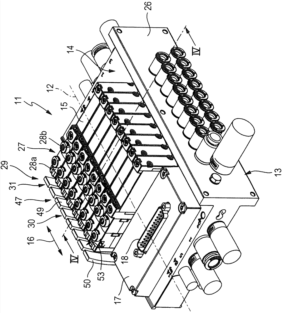
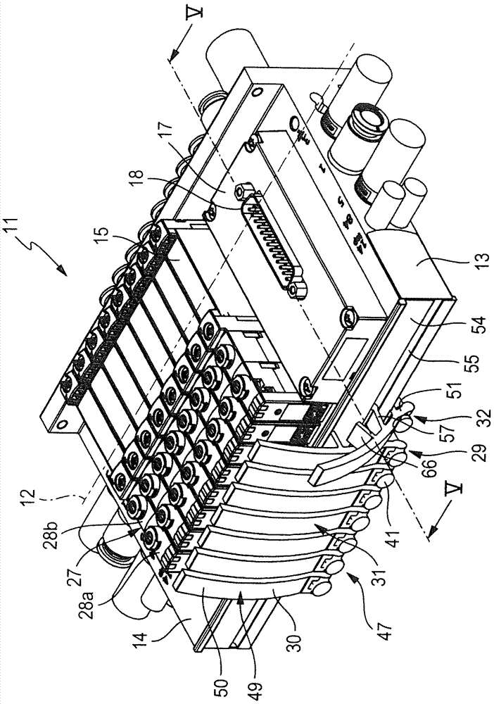
[0034]A preferred construction of the valve cell, indicated in its entirety by the reference numeral 11, comprises a fluid distributor 13 extending in the direction of the longitudinal axis 12, which is equipped with a plurality of in particular electrically actuatable controls on the first mounting surface 14. valve 15. The control valves 15 are arranged one behind the other in a serial direction 16 , indicated by the double arrows, which coincides with the longitudinal axis 12 . Likewise, the electronics module 17 is placed laterally on the first mounting surface 14 , for example beside the string of control valves 15 .
[0035] On its upper side, the electronics module 17 has an electrical connection 18 via which a control signal for controlling the valve 15 can be introduced. as especially in Figure 4 As shown in , the circuit board assembly 19 is located inside the fluid distributor 13 , which extends in the direction of the longitudinal axis 12 of the valve cell 11 . If the control valve 15 is inserted into its equipped position on the first mounting surface 14 , a connection to the printed circuit board assembly 19 is simultaneously established via the contact pins 20 arranged on the underside of the respective control valve 15 . The circuit board assembly 19 extends laterally beyond the installation position of the control valve 15 into the region of the installation position of the electronics module 17 , in which area contacting with the electronics module 17 takes place.
[0036] The fluid distributor 13 is shown as a single piece by way of example, but alternatively it is also possible to form the fluid distributor 13 from a plurality of modular pieces which are likewise arranged one behind the other in the series direction 16 .
[0037] The fluid distributor 13 is connected in its longitudinal direction 12 with at least one common input channel 21 for all control valves 15 ( Figure 4 ) through. Parallel to this common inlet channel 21 , a first and a second common exhaust channel 22 , 23 extend in the fluid distributor 13 , which, like the common inlet channel 21 , each exit several times relative to the first mounting surface 14 , Each control valve 15 is thus connected to a common inlet channel 21 and each of the exhaust channels 22 , 23 .
[0038] Each control valve 15 is also in communication with, in the example case, two separate working channels 24 , 25 specifically associated with the control valves, which pass through the fluid distributor 13 transversely to the longitudinal axis 12 and respectively on the one hand in the first One exits at the mounting surface 14 and the other opens with respect to a coupling surface 26 located outside the fluid distributor 13 . as especially in figure 1 As shown in , the common feed channel 21 not only extends along the longitudinal axis 12 , but also has a branch which extends transversely to the longitudinal axis 12 and exits at the connecting surface 26 . In the exemplary case, the exhaust ducts 22 , 23 run parallel to the longitudinal axis 12 and likewise each have a branch which exits at the connecting surface 26 .
[0039] The control valves 15 are expediently pilot-controlled valves with each an electrically actuatable pilot valve device 27 , for example a solenoid valve device. Each pilot valve arrangement 27 may consist of one or two electrically actuatable pilot valves 28a, 28b, wherein, in the exemplary case, each pilot valve arrangement 27 has two identical valves in the associated control valve 15. The pre-control valves 28a, 28b are arranged at the side.
[0040] The valve cell 11 also has a safety valve arrangement 29 with at least one safety valve 30 which can be switched selectively between an open position 31 and a shut-off position 32 which shuts off the supply of pressure medium to the associated control valve 15 . An individual supply channel 33 for each control valve 15 branches off from the common supply channel 21 , via which the individual control valve 15 is supplied with pressure medium. In the example case the pilot control valves 28 a , 28 b are also supplied with control air via a separate supply channel 33 . A safety valve arrangement 29 with at least one safety valve 30 is engaged in one or more supply channels 33 .
[0041] As especially in the first embodiment according to the present invention figure 2 As can be seen in , the safety valve arrangement 29 has, for example, a rectangular base module 34 into which a plurality of safety valves 30 , in particular corresponding to the number of control valves 15 , are integrated. Meanwhile, according to the first embodiment, each control valve 15 is associated with a safety valve 30 .
[0042] as especially in figure 2 As shown in , the base module 34 has an abutment surface 35 against which a second mounting surface 36 formed on the underside of the fluid distributor 13 abuts and is fastened there. as especially in Figure 7 or also Figure 8 As shown in , various coupling holes are located at the mating surface 35 which, in the illustrated installed state of the base module 34 , are connected to the corresponding outlets at the bottom side of the fluid distributor 13 or at the second mounting surface 36 is connected.
[0043] as especially in Figure 4 and Figure 5 As shown in the example of a single safety valve 30 , the individual supply channels 33 lead away from the central, common supply channel 21 extending along the longitudinal axis 12 . The separate supply channel 33 has a first channel section 37 extending approximately in the vertical direction, which exits from the supply channel 21 at the second mounting surface 36 with a connecting hole.
[0044] likewise especially in Figure 4 As shown in , the safety valve 30 each has a valve element 38 in the form of a valve slide which can be positioned selectively in the open position 31 or in the closed position 32 , which is accommodated in the transverse direction in the base module 34 In the slide receptacle 39 extending in the longitudinal axis 12 of the fluid distributor 13 . It is characterized in that the valve slide has a switching section 40 which is movably guided in the slide receptacle 39 and has an actuating section 41 protruding from the slide receptacle 39 . According to the exemplary embodiment shown, the switching section 40 and the actuating section 41 are separated from each other by an annular stop 42 protruding radially on the outer circumference of the actuating section 41 . The switching section 40 has three annular sections 43a-c, each provided with a sealing ring, wherein adjacent annular sections 43a-c are connected to one another by web sections 44a, 44b of reduced diameter.
[0045] as especially in Figure 4 As shown in FIG. 2 , a separate supply channel 33 extends into a slider receptacle 39 . as especially in Figure 7 and 8 As shown in , the abutment surface 35 of the base module 34 has further coupling holes from which the second channel section 45 of the supply channel 33 is oriented obliquely in the first fluid distributor 13 , for example. It extends in the direction of the mounting surface 14 . Furthermore, a third channel section 46 is provided, which is used to supply the pilot control valves 28 a , 28 b with control air and also extends transversely in the fluid distributor 13 in the direction of the first mounting surface 14 in the exemplary case.
[0046] The separate supply channel 33 then slides on the base module 34 and on the slide receptacle 39 with the valve slide mounted therein. Depending on the switching position of the valve slide, the passage between the first channel section 37 and the second and third channel sections 45 , 46 is open or blocked.
[0047] The safety valve arrangement 29 has a pivot device 47 via which at least one safety valve 30 can be switched between an open position and a closed position 31 , 32 by means of a pivot actuation.
[0048] The pivot device 47 has at least one pivot lever 49 pivotable about a pivot axis 48 by means of a pivot bearing, the pivot movement of which can be converted to the valve element 38 which can be positioned selectively in the open position 31 or in the closed position 32 .
[0049] as especially in Figure 4 As shown in , the pivot lever 49 has a first lever arm 50 which is arranged on one side of the pivot axis 48 and is free to close, and a second lever arm 51 which is arranged on the other side of the pivot axis 48 . In the exemplary case, the first lever arm 50 is substantially longer than the second lever arm 51 . The pivot lever 49 has a convexly curved front side 52 and a rear side 53 correspondingly extending parallel to the front side 52 . The pivot lever 49 is associated with a mounting surface 54 opposite the coupling surface 26 . The pivot axis 48 of the pivot lever 49 is located in the region of this mounting surface 54 .
[0050] A bearing receptacle 55 in the form of a bearing groove running parallel to the longitudinal axis 12 of the fluid distributor 13 is provided as a pivot bearing for the pivotable bearing of the pivot lever 49 . The bearing groove has an approximately circular cross section with a narrowing slit, with which the bearing groove opens out at the mounting surface 54 . The pivot bearing also has a bearing pin 56 , which is mounted so as to be pivotable in a bearing receptacle or bearing groove. The bearing pin 56 and the bearing groove thus form a rotary joint for the pivot lever 49 . The bearing pin 56 is part of a bearing web 57 oriented obliquely downward from the rear side 53 of the pivot lever 49 in the region of the second lever arm 51 , which extends essentially over the entire width of the pivot lever 49 . The bearing web 57 has a base section 58 which is expediently placed in one piece on the rear side 53 of the pivot lever 49 and has a bearing pin 56 connected in particular to the base section 58 in one piece, which bearing pin 56 It also has a longitudinal extension oriented in the direction of the longitudinal axis 12 . The bearing pin 56 has a circular cross section complementary to the design of the bearing groove, so that the bearing pin can be inserted laterally into the bearing groove.
[0051] The coupling means for coupling the pivot lever 49 to the valve element 38 has a bearing hole 59 formed on the second lever arm 51 , which is pierced by a cylindrical bearing section 60 on the actuating section 41 of the valve element 38 . Pass. The pivoting movement of the pivoting lever 49 is thus converted into a linear movement of the valve element 38 .
[0052] The pivoting device 47 also has a locking element 61 for releasably locking the pivoting lever 49 in the closed position 32 . The latching part 61 comprises a longitudinally extending latching nose 62 formed in the region of the mounting surface 54 on the bottom edge of the fluid distributor 13 and is inclined from the rear side 53 of the pivot lever 49 in the region of the second lever arm 51 . A downwardly extending latch receptacle 63 with a latch groove 64 . On the swing lever 49 from the Figure 4 The open position 31 shown in the movement to the Figure 5 In the case of the closed position 32 shown in , the detent groove 64 snaps into the detent nose 62 , thereby fixing the closed position securely in place.
[0053] The pivot lever 49 also has a stop 65 which defines a defined position of the open position 31 when the pivot lever is pivoted out of the closed position 32 . The stop 65 includes a stop web 66 that projects away from the rear side 53 in the region of the first lever arm 50 , which abuts against the mounting surface 54 in the open position 31 and thereby defines the open position 31 .
[0054] in order to be in Figure 4 Switching the safety valve 30 in the open position 31 to the closed position 32, the user grasps the first lever arm 50 of the swing lever 49 and swings the swing lever 49 around the swing axis 49 with the first lever arm 50 away from the fluid dispensing Device 13. In this case, the second lever arm 51 is logically pivoted towards the fluid distributor 13 . In this case, the second lever arm 51 presses the actuating section 51 of the valve slide inwardly by means of the coupling formed at the bearing bore 49 until the stop 42 abuts against the outer surface of the base module 34 . In this case, the detent groove on the pivot lever 49 snaps into the detent nose 62 on the fluid dispenser 13 . By moving the actuating section 41 , the integrally coupled switching section 40 of the valve element 38 is also forced to move, wherein the second annular section 43 b closes off the first channel section 37 from the second and third channel regions. Passage between segments 45,46. The supply pressure supplied via the supply channel 21 can thus no longer reach the associated control valve 15 via the separate supply channel 33 which has just been blocked. It is thus possible to replace the control valve 15 during operation without interrupting the fluid loading of adjacent valves.
[0055] In order to make the swing lever 49 move back, that is in order to Figure 5 The shutoff position shown in 32 to the Figure 4 To switch between the open position 31 shown in , the user grasps the first lever arm 50 of the pivot lever 49 and swivels it back in the direction of the fluid dispenser 13 , wherein the detent groove 64 emerges from the detent nose 62 card out. The pivoting movement continues until the stop web 66 strikes the mounting surface 54 , whereby the exact open position 31 is reached.
[0056] Image 6 A second embodiment of a valve cell 11 according to the invention is shown, which differs from the aforementioned first embodiment in that, instead of the base module 34 housing a plurality of safety valves 30 , a single module 67 is used, into which a single safety valve 30 is integrated. Single module 67 in.

PUM

no PUM

Description & Claims & Application Information

We can also present the details of the Description, Claims and Application information to help users get a comprehensive understanding of the technical details of the patent, such as background art, summary of invention, brief description of drawings, description of embodiments, and other original content. On the other hand, users can also determine the specific scope of protection of the technology through the list of claims; as well as understand the changes in the life cycle of the technology with the presentation of the patent timeline. Login to view more.
Why Eureka
Try Eureka