Optical object, optical-film laminate, and process for producing optical object

A manufacturing method and technology for an optical body, applied in the field of optical bodies, can solve the problems of insufficient protection of concave-convex structure, deterioration of anti-reflection film performance, detachment of protective film, etc., and achieve the effects of suppressing light reflection, suppressing defects, and improving operability

Active Publication Date: 2017-08-29
DEXERIALS CORP
View PDF6 Cites 28 Cited by
  • Summary
  • Abstract
  • Description
  • Claims
  • Application Information

AI Technical Summary

Problems solved by technology

If the adhesive remains on the concave-convex structure, the adhesive will degrade the performance of the anti-reflection film
As a solution to this problem, it is conceivable to reduce the adhesiveness of the adhesive, but this method will easily detach the protective film from the concave-convex structure
That is, there is a possibility that the protection of the concave-convex structure by the protective film becomes insufficient.

Method used


Image

  • Optical object, optical-film laminate, and process for producing optical object
  • Optical object, optical-film laminate, and process for producing optical object
  • Optical object, optical-film laminate, and process for producing optical object

Examples


Embodiment 1

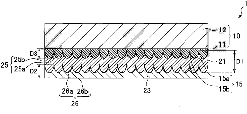
[0187] In Example 1, the optical body 1 was produced according to the following process. A PET film with a thickness of 50 μm was prepared as the base film 12 . In addition, an ultraviolet-curable acrylic resin (Dexerials Co., Ltd., SK1100 series) to which a silicone-based mold release agent (BYK company, silicone lubricant BYK333) was added was prepared as a photocurable resin. Then, the uncured resin layer 11p for main films is formed on the base film 12 by apply|coating photocurable resin on the base film 12. In addition, the first master disk 30 is fabricated using the exposure apparatus 200 described above. Then, by pressing the circumferential surface of the first original disc 30 to the main film uncured resin layer 11p, the fourth concave-convex structure 32 formed on the circumferential surface of the first master disc 30 is transferred to the main film uncured resin layer. 11p. Then, by curing the uncured resin layer 11p for the main film, the concave-convex resin...

Embodiment 2

[0201] Except that the refractive index of the adhesive layer 23 was 1.7 and the refractive index of the adherend 502 was 1.7, the same process as in Example 1 was performed to calculate the spectral reflection spectrum of the optical film bonded body. The results are shown in Table 7B. Also in Example 2, almost the same results as in Example 1 were obtained.

Embodiment 3

[0207] Except having made the refractive index of the adhesive bond layer 23 1.75, and the refractive index of the to-be-adhered body 502 were 1.75, the same process as Example 1 was performed, and the spectral reflection spectrum of the optical film bonded body was calculated. The results are shown in Table 7C. Also in Example 3, almost the same results as in Example 1 were obtained.


PUM

PropertyMeasurementUnit
thicknessaaaaaaaaaa
thicknessaaaaaaaaaa
thicknessaaaaaaaaaa

Abstract

To provide: a novel and improved optical object in which the rugged structure of the optical film can be protected without requiring the use of a protective film, the optical film can have a reduced thickness, the handleabilty can be improved, the occurrence of a trouble attributable to a difference in refractive index between an adhesive layer and the optical film is inhibited, and the optical film can be more tenaciously adhered to an adherent; an optical-film laminate; and a process for producing the optical object. The optical object according to the present invention comprises an optical film equipped with a first rugged structure formed in one surface thereof and a second rugged structure formed in the other surface and a master film covering the first rugged structure, wherein the first rugged structure has an average ruggedness period which is not greater than the wavelengths of visible light and the master film is equipped with a third rugged structure that has been formed in the surface facing the first rugged structure and that has a shape reverse to that of the first rugged structure.

Description

technical field [0001] The invention relates to an optical body, an optical film bonding body and a manufacturing method of the optical body. Background technique [0002] An optical film formed with a concavo-convex structure in which the average period of concavo-convex is equal to or less than the wavelength of visible light has an excellent antireflection effect on light in the wavelength range of visible light. Therefore, an optical film having a concavo-convex structure can be used as, for example, an antireflection film. This concave-convex structure is also called a moth-eye structure. For example, Patent Documents 1 to 2 disclose an optical film having a concavo-convex structure. [0003] As a method of forming a concave-convex structure, for example, Patent Document 1 discloses an optical nanoimprint method. In the photonanoimprint method, a master disk for forming a concave-convex structure on the surface is prepared. And, by coating the uncured photocurable r...

Claims


Application Information

Patent Timeline
Patent Type & Authority Applications(China)
IPC IPC(8): G02B1/118B32B3/30B32B7/02
CPCG02B1/118B29D11/00788B29D11/00288G03F7/0002B32B3/30G02B1/111B32B7/12B32B27/08B32B37/025B32B2305/72B32B2307/40B32B2309/105
Inventor 梶谷俊一
Owner DEXERIALS CORP
Why Eureka
Try Eureka