Shaft inserting mechanism

A technology of inserting mechanism and turning mechanism, applied in metal processing equipment, metal processing, manufacturing tools, etc., can solve the problems of difficult to guarantee assembly quality, low efficiency of manual assembly, etc., and achieve easy assembly product quality, saving labor costs, and degree of automation high effect

Inactive Publication Date: 2017-09-01
林育键
View PDF6 Cites 1 Cited by
  • Summary
  • Abstract
  • Description
  • Claims
  • Application Information

AI Technical Summary

Problems solved by technology

[0002] At present, the motor rotor assembly industry is done manually, and manual assembly has problems such as low efficiency and difficult assembly quality assurance.

Method used


Image

  • Shaft inserting mechanism
  • Shaft inserting mechanism
  • Shaft inserting mechanism

Examples


Embodiment Construction

[0015] The preferred embodiments of the present invention are described in detail below, so that the advantages and features of the present invention can be more easily understood by those skilled in the art, so as to define the protection scope of the present invention more clearly.

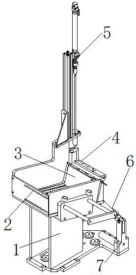
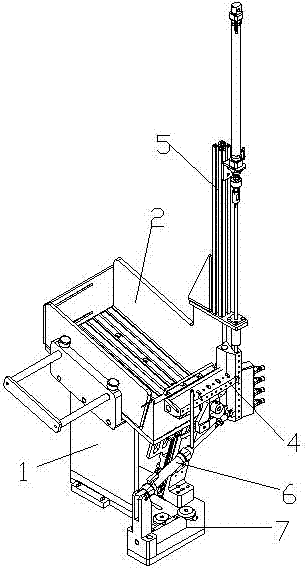
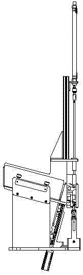
[0016] The present invention describes a shaft insertion mechanism, such as figure 1 combine figure 2 , image 3 and Figure 4 As shown, it includes a frame 1, a shaft storage mechanism 2, a shaft pushing slide table 3, a shaft turning mechanism 4 and a shaft pressing mechanism 5, and the shaft storage mechanism 2 is arranged on the top of the frame 1. And the shaft storage mechanism 2 is arranged on the top of the frame 1 in an inclined structure, the push shaft loading slide table 3 is horizontally arranged on the inner side of the lower end of the shaft storage mechanism 2, and the shaft storage mechanism The shaft overturning mechanism 4 is correspondingly provided at the top edge outsid...


PUM


Abstract

The invention discloses a shaft inserting mechanism which comprises a rack, a shaft storage mechanism, a shaft pushing feeding sliding table, a shaft overturning mechanism and a shaft pressing mechanism, wherein the shaft storage mechanism is arranged on the top of the rack and is arranged at the upper part of the rack in an inclined structural form; the shaft pushing feeding sliding table is arranged horizontally on the inner side of the lower end part of the shaft storage mechanism; the shaft overturning mechanism is correspondingly arranged on the edge of the top part of the outer side of the lower end part of the shaft storage mechanism; the shaft pressing mechanism is correspondingly arranged above the shaft overturning mechanism. The shaft inserting mechanism is high in automation degree, the quality of an assembly product is easily guaranteed, and the labor cost is reduced; and meanwhile, the production efficiency is improved, and the enterprise benefit is improved.

Description

technical field [0001] The invention relates to the motor rotor assembly industry, in particular to a shaft insertion mechanism. Background technique [0002] At present, the motor rotor assembly industry is done manually, and manual assembly has problems such as low efficiency and difficult assembly quality assurance. Contents of the invention [0003] The purpose of the present invention is to provide a shaft insertion mechanism with high degree of automation, easy assurance of assembled product quality, saving labor cost, improving production efficiency and benefiting enterprises. [0004] The technical solution of the present invention is that a shaft insertion mechanism includes a frame, a shaft storage mechanism, a push shaft feeding slide, a shaft turning mechanism and a shaft pressing mechanism, and the shaft storage mechanism is arranged on the frame and the shaft storage mechanism is arranged above the frame in an inclined structure, the push shaft feeding slide...

Claims


Application Information

Patent Timeline
Patent Type & Authority Applications(China)
IPC IPC(8): B23P19/02B23P19/00
CPCB23P19/004B23P19/02
Inventor 余少华许成陆小勇
Owner 林育键
Why Eureka
Try Eureka