
A Machining Method of Complicated Curved Surface of Brittle Material

A technology for brittle materials and complex curved surfaces, applied in stone processing equipment, fine working devices, manufacturing tools, etc., can solve problems such as low processing efficiency, easy embedding of abrasives, and failure of optical functions, so as to improve the quality of processed surfaces and reduce tool damage. Abrasion, reduced difficulty effects

Active Publication Date: 2019-05-10
TIANJIN UNIV
View PDF8 Cites 0 Cited by
  • Summary
  • Abstract
  • Description
  • Claims
  • Application Information

AI Technical Summary

Problems solved by technology

However, the grinding method uses tiny abrasive particles to repeatedly grind the optical device into shape, the processing efficiency is low, and for soft and brittle materials, abrasives are easy to embed into the interior to form impurities and defects, which in turn cause the failure of optical functions

Method used


Image

  • A Machining Method of Complicated Curved Surface of Brittle Material
  • A Machining Method of Complicated Curved Surface of Brittle Material
  • A Machining Method of Complicated Curved Surface of Brittle Material

Examples


specific Embodiment approach

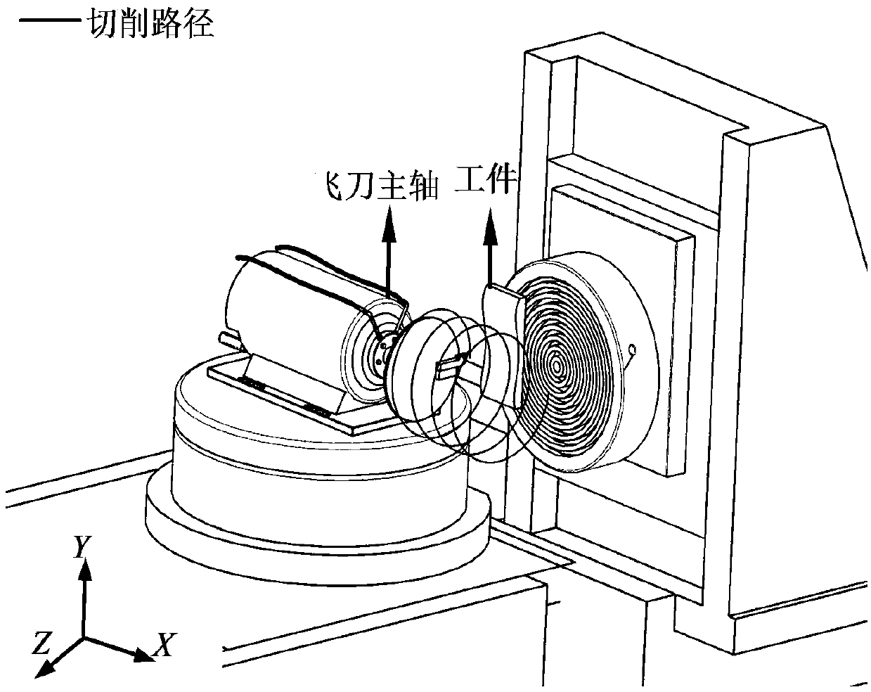
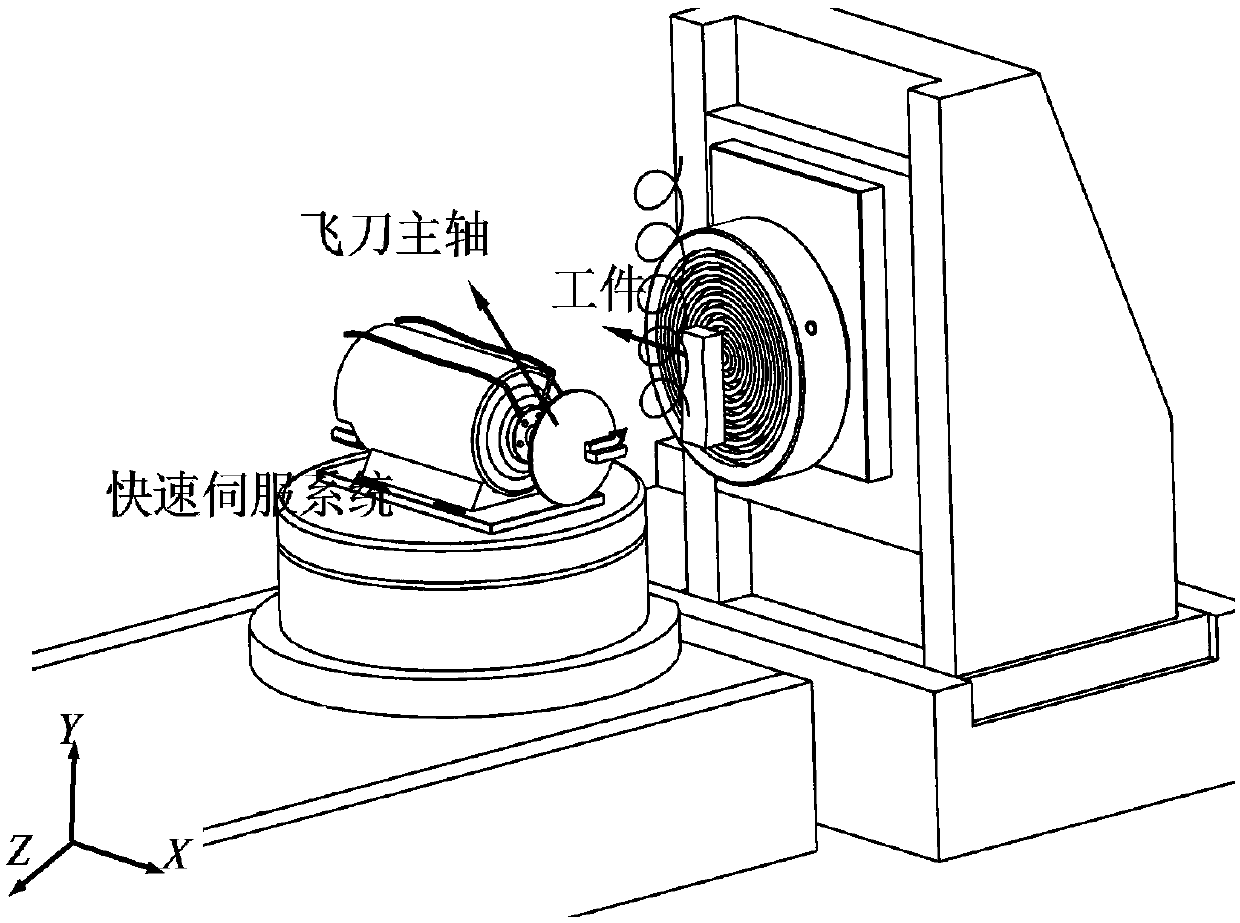
[0025] 1. Build a processing system combining milling and flying tools;

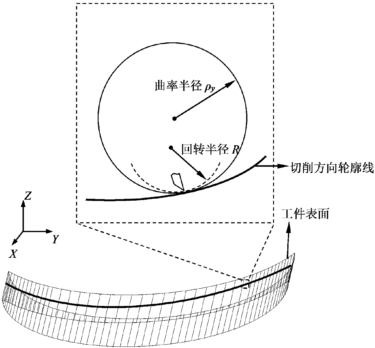
[0026] 2. Select the appropriate radius of rotation of the flying tool spindle and the appropriate milling feed direction to avoid the corresponding radius of curvature being smaller than the radius of rotation of the flying tool, that is, select the appropriate milling spindle speed, feed rate and radius of rotation of the flying tool installation to avoid flying The radius of gyration of the tool is greater than the maximum radius of curvature on any one of its curved surfaces along the linear motion direction of the milling axis.

[0027] 3. According to the characteristics of the processing process and the cutting performance of the material, design suitable cutting parameters and tool geometry parameters; according to the embodiment, select the flying knife spindle speed to be 4000rpm, the radius of gyration to be about 30mm, and the nose radius to be 0.5mm. The directional feed is F=2mm / min, and wh...


PUM


Abstract

The invention relates to a processing method of a complicated curve surface of a fragile material. The processing method comprises the steps that according to the shape of a surface to be processed, an appropriate fly cutter spindle turning radius and an appropriate milling feeding direction, and a fly cuter turning spindle can be selected to be parallel to the milling feeding direction or perpendicular to the milling feeding direction; according to the processing process characteristics and the cutting characteristics of a material, appropriate cutting parameters and appropriate cutting tool geometric parameters are design so as to guarantee that the removal amount of the material in single-pass cutting is controlled within a plastic removal rang; based on the cutting parameters and the cutting tool geometric parameters, a processing path of fly cutter cutting and milling feeding is generated, and path compensation is conducted before processing, and after compensation, the contour of a cutting tool traverses the path to form a processed surface; a workpiece to be processed is mounted on a spindle of an ultra-precision machine tool, and a fly cutter is perpendicularly mounted on an ultra-precision milling shaft; and the workpiece is processed.

Description

technical field [0001] It belongs to the field of complex curved surface manufacturing and ultra-precision machining of brittle materials. Background technique [0002] Optical complex surfaces are widely used in new energy, aerospace, lighting imaging, bioengineering and other interdisciplinary fields. Compared with the traditional optical surface, the optical complex curved surface has superior performance, its curved surface has a large degree of freedom, a better viewing angle, fewer components required for the system, lighter, easier to assemble, and a higher modulation transfer function. As the core component of many optical devices, adding complex curved surfaces can reduce the volume and weight of the system while improving the imaging quality of the system. Semiconductor materials, optical crystals and other brittle materials have excellent ultraviolet or infrared transmittance, high damage threshold, high refractive index and other characteristics, and the demand ...

Claims


Application Information

Patent Timeline
Patent Type & Authority Patents(China)
IPC IPC(8): B28D5/00B28D7/00
CPCB28D5/0058B28D7/005
Inventor 房丰洲张效栋李泽骁朱琳琳
Owner TIANJIN UNIV
Learn More