Fan housing for engine cooling module and control method of fan housing

An engine cooling and cooling fan technology, which is applied in the direction of engine cooling, coolant flow control, engine components, etc., can solve the problem of uncontrollable opening time and opening size of the grille, the opening area of ​​the fan cover cannot be changed, and the cooling can not be satisfied. Air flow requirements and other issues to achieve the effect of delaying intervention work time, improving NVH performance, and reducing rotational speed

Inactive Publication Date: 2017-09-01
TONGJI UNIV
View PDF9 Cites 2 Cited by
  • Summary
  • Abstract
  • Description
  • Claims
  • Application Information

AI Technical Summary

Problems solved by technology

[0005] At present, the fan cover used in the front-end cooling module of the car is usually closed and fixed, and the opening area of ​​the fan cover cannot be changed
Some fan covers use passive opening grilles, which can only be opened by the airflow at a certain speed, and the opening time and opening size of the grilles are uncontrollable, which cannot meet the actual cooling airflow flow requirements

Method used


Image

  • Fan housing for engine cooling module and control method of fan housing
  • Fan housing for engine cooling module and control method of fan housing
  • Fan housing for engine cooling module and control method of fan housing

Examples


Embodiment 1

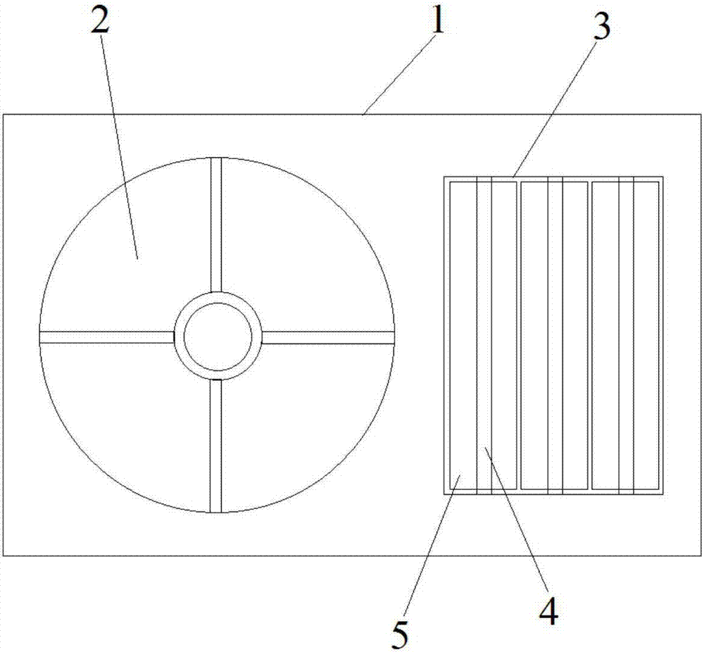
[0035] Such as figure 1 Shown is a fan cover for the engine cooling module, the fan cover is located between the cooling fan and the radiator, the fan cover includes a fan cover main body 1, a cooling fan that is set on the fan cover main body 1 and is adapted to the cooling fan The fan vent 2, the grille vent 3 provided on the main body of the fan cover 1 and the controller, the grille vent 3 are arranged side by side with three active grille assemblies electrically connected to the controller respectively, and the controller passes through the active grille The grill assembly controls the opening size of the grill vents 3 .

[0036] Wherein, the active grille assembly is a louver-type structure, and the active grille assembly includes a rotating shaft 4 arranged in the grille vent 3, a grille plate 5 arranged on the rotating shaft 4, and a rotating shaft stepping motor connected to the rotating shaft 4 , the rotating shaft stepping motor is electrically connected with the c...

Embodiment 2

[0049] In this embodiment, two active grill components are arranged side by side in the grille vent 3 and are respectively electrically connected to the controller. The length of the grille vent 3 is 300 mm, and the width is 110 mm.

Embodiment 3

[0051] In this embodiment, five active grill components are arranged side by side in the grille vent 3 and are respectively electrically connected to the controller. The length of the grille vent 3 is 310mm, and the width is 90mm.


PUM

PropertyMeasurementUnit
Lengthaaaaaaaaaa
Widthaaaaaaaaaa
Lengthaaaaaaaaaa

Abstract

The invention relates to a fan housing for an engine cooling module and a control method of the fan housing. The fan housing comprises a fan housing main body, a cooling fan ventilating opening formed in the fan housing main body, a grid ventilating opening and a controller; and the grid ventilating opening is internally provided with a plurality of driving grid assemblies electrically connected with the controller correspondingly in parallel, and the controller controls the opening magnitude of the grid ventilating opening through the driving grid assemblies. According to the driving condition of an automobile, the cooling airflow flow required by the cooling module and the actual cooling airflow flow are calculated, the cooling fan rotation speed and the opening of the driving grid assemblies are controlled through the controller, and the requirement for the cooling airflow flow is met. Compared with the prior art, the opening magnitude of the grid ventilating opening in the fan housing is controlled through the driving grid assemblies so as to change the circulation area of the cooling airflow, and real-time control over the cooling airflow flow in the engine cooling module is achieved; and besides, the rotation speed of a cooling fan can be the minimum, energy is saved, consumption is lowered, and the NVH performance of the whole automobile is improved.

Description

technical field [0001] The invention belongs to the technical field of automobile front-end components, and relates to a fan cover for an engine cooling module and a control method thereof. Background technique [0002] Automotive front-end components usually include three parts: front-end structural parts, headlight modules, and cooling modules. Among them, the front-end structural parts and cooling modules are components that have an important impact on the gas flow in the engine compartment. The front-end grille of a car is an important front-end structural part. It plays the role of guiding airflow into the engine compartment and protecting cooling components such as radiators. The distribution of the flow field has an important influence. The cooling module mainly includes a condenser, radiator, cooling fan, etc. Among them, the cooling fan is a component used in the automotive cooling module to encourage air recirculation in the car, enhance the heat exchange capacity...

Claims


Application Information

Patent Timeline
IPC IPC(8): F01P5/06F01P7/10
CPCF01P5/06F01P7/04F01P7/10F01P2005/046
Inventor 李田田刘晓辉王建新朱志军
Owner TONGJI UNIV
Why Eureka
Try Eureka