Cross-flow fan and air conditioner

A technology of cross-flow fan blades and air conditioners, applied in the field of air conditioners, can solve the problems of a single air outlet, the limited angle of the upward and downward adjustment of the guide vanes, and the limited adjustment range of the guide vanes, so as to improve comfort, uniform and rapid temperature rise, and uniformity. and rapid cooling effect

Pending Publication Date: 2017-09-01
GREE ELECTRIC APPLIANCES INC
View PDF6 Cites 1 Cited by
  • Summary
  • Abstract
  • Description
  • Claims
  • Application Information

AI Technical Summary

Problems solved by technology

[0002] At present, the air conditioners developed at home and abroad are generally air conditioners with a single air outlet, that is, the cooling mode and the heating mode are all blown out by a single air outlet. The air outlet direction of the air conditioner is controlled by controlling the upward or downward angle of the guide vanes, but the angle of the guide vanes can be adjusted up and down, and the air outlet itself has a certain orientation. Hot air can only be controlled within a small range of angles
[0003] Due to the difference in the density of cold air and hot air, in order to further improve the comfort of the air conditioner, it is necessary to control the flow direction of the cold air and hot air so that they flow in completely different directions, but the existing air conditioners have limited adjustment range due to guide vanes. As a result, in the case of heating or cooling, it is no longer possible to further improve the control of the angle of cold or hot air blown out of the air outlet, and thus fail to meet people's higher requirements for the comfort of air conditioners

Method used


Image

  • Cross-flow fan and air conditioner
  • Cross-flow fan and air conditioner
  • Cross-flow fan and air conditioner

Examples


Embodiment Construction

[0032] The present invention will be described in detail below with reference to the accompanying drawings and examples.

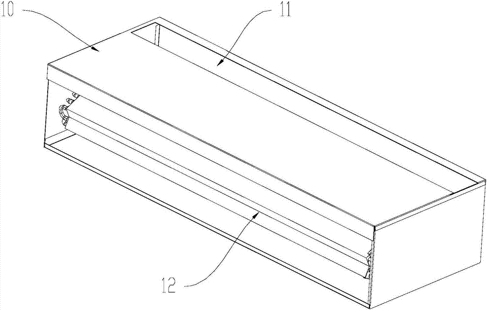
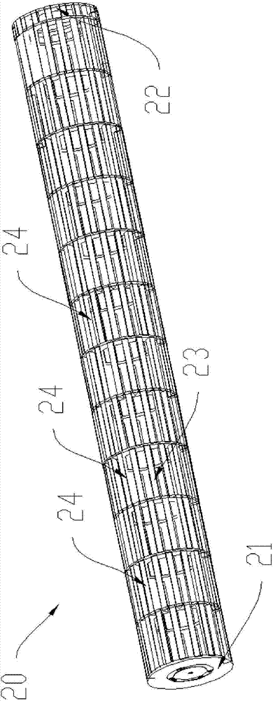
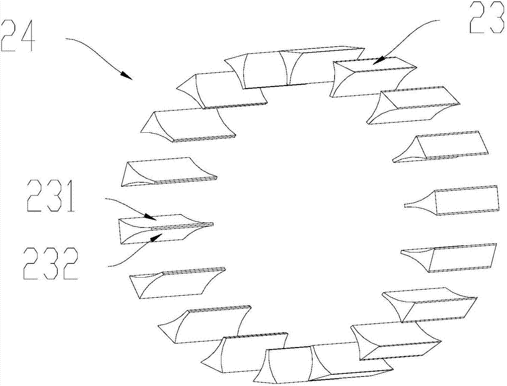
[0033] Such as figure 1 , figure 2 , Figure 4 As shown, according to the structural diagram of the internal unit of the air conditioner of the present invention, the structural diagram of the cross-flow vane 20 in the interior unit of the air-conditioner according to the present invention, and the cross-section of a blade unit 24 in the cross-flow vane 20 of the present invention Schematic diagram, an air conditioner is proposed in an embodiment of the present invention, and the air conditioner includes: a housing 10 having a first air outlet 11 and a second air outlet 12 on the housing 10, the first air outlet 11 faces a first preset direction, and the second air outlet The second tuyere 12 faces the second preset direction; the cross-flow vane 20 arranged inside the casing 10, the blade 23 of the cross-flow vane 20 has a first side 231 and a second s...


PUM


Abstract

The invention provides a cross-flow fan and an air conditioner, and relates to the technical field of air conditioners. The air conditioner comprises a shell and the cross-flow fan arranged on the shell; the shell is provided with a first air opening and a second air opening, the first air opening faces a first preset direction, and the second air opening faces a second preset direction; the cross-flow fan is arranged inside the shell, a blade of the cross-flow fan is provided with a first side face and a second side face opposite to the first side face; the air conditioner at least has two working states; in the first working state, the cross-flow fan rotates clockwise to enable air flow to pass through the cross-flow fan and then flows out from the first air opening; and in the second working state, the cross-flow fan rotates anticlockwise to enable air flow to pass through the cross-flow fan and then flows out from the second air opening. By means of the cross-flow fan and the air conditioner, the air outlet direction of an air outlet of the air conditioner can be effectively changed in the refrigeration and heating modes.

Description

technical field [0001] The invention relates to the field of air conditioners, in particular to a cross-flow fan blade and an air conditioner. Background technique [0002] At present, the air conditioners developed at home and abroad are generally air conditioners with a single air outlet, that is, the cooling mode and the heating mode are all blown out by a single air outlet. The air outlet direction of the air conditioner is controlled by controlling the upward or downward angle of the guide vanes, but the angle of the guide vanes can be adjusted up and down, and the air outlet itself has a certain orientation. Hot air can only be controlled within a small range of angles. [0003] Due to the difference in the density of cold air and hot air, in order to further improve the comfort of the air conditioner, it is necessary to control the flow direction of the cold air and hot air so that they flow in completely different directions, but the existing air conditioners have l...

Claims


Application Information

Patent Timeline
IPC IPC(8): F24F1/00F24F13/14
CPCF24F1/0011F24F13/1413
Inventor 曹颖陈博强邓晶杨亮林国游王云亮孔环灵邵元浩
Owner GREE ELECTRIC APPLIANCES INC
Why Eureka
Try Eureka