Connected heat transfer device

A heat pipe, a heat pipe technology, applied in the direction of semiconductor/solid-state device parts, semiconductor devices, electrical components, etc., can solve the problem that the heat dissipation effect has not been fully exerted

Active Publication Date: 2019-04-16
COOLER MASTER CO LTD
View PDF7 Cites 0 Cited by
  • Summary
  • Abstract
  • Description
  • Claims
  • Application Information

AI Technical Summary

Problems solved by technology

[0004] However, the heat conduction plate and the heat pipe in the existing heat transfer device operate independently, and the capillary structure of the heat conduction plate is not connected with the capillary structure of the heat pipe, so that each is only the heat conduction plate and the heat pipe in terms of the heat conduction plate or the heat pipe. Individual heat transfer instead of integral heat transfer, in other words, the heat dissipation effect has not been fully utilized

Method used


Image

  • Connected heat transfer device
  • Connected heat transfer device
  • Connected heat transfer device

Examples


Embodiment Construction

[0047] The detailed description and technical content of the present invention are described below with accompanying drawings. However, the drawings are provided for reference and illustration only, and are not intended to limit the present invention.

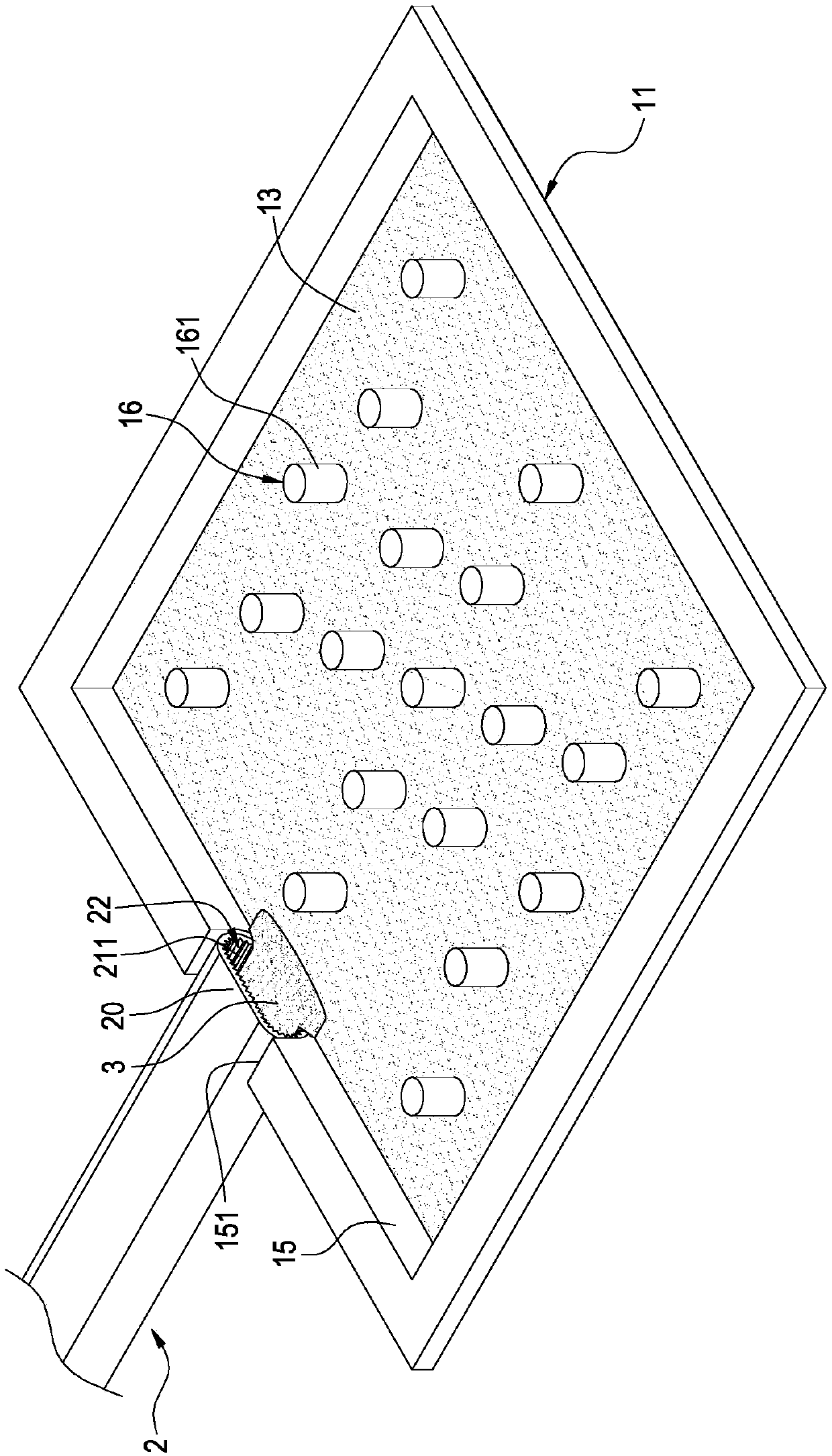
[0048] The invention provides a connected heat transfer device, such as Figure 1 to Figure 7 Shown is a first embodiment of the invention, as Figure 8 ~ Figure 10 Shown is a second embodiment of the invention.

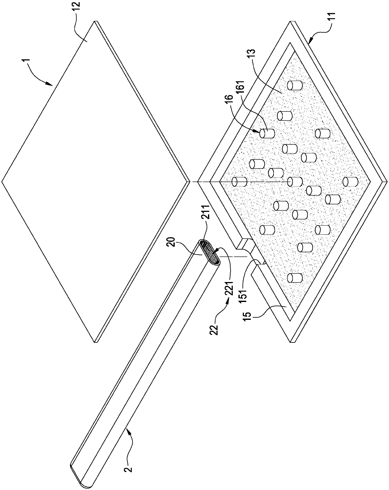
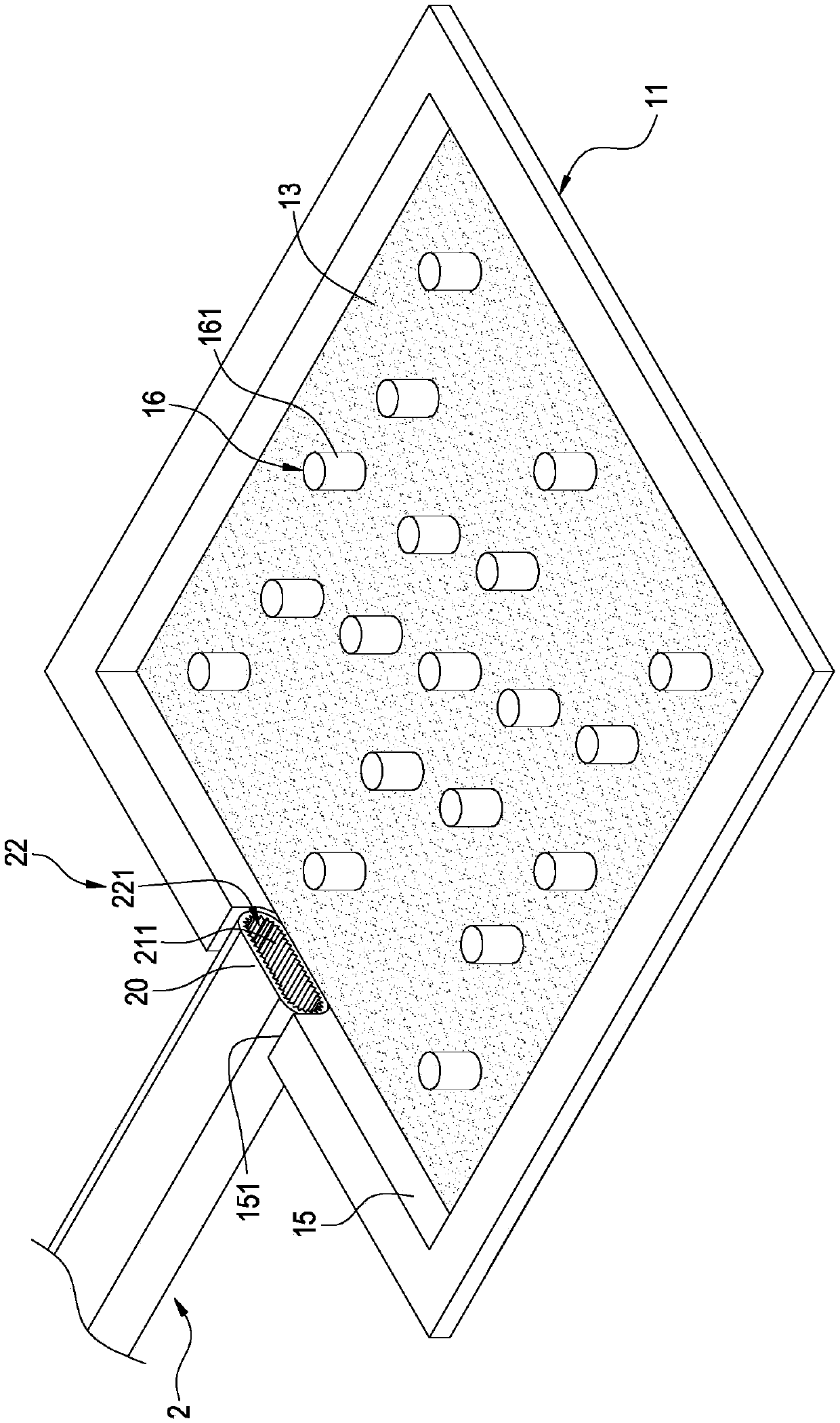
[0049] Such as Figure 1 to Figure 7 As shown, the first embodiment of the communication type heat transfer device of the present invention includes: a vapor chamber 1 and at least one heat pipe 2, and of course a working fluid flowing between the chamber 1 and the heat pipe 2 ( not shown in the figure).

[0050] The temperature chamber 1 has a bottom plate 11 and a cover plate 12 opposite to each other, and a chamber 10 is formed after the combination between the bottom plate 11 and the cover plate 12 (see Figur...


PUM


Abstract

The invention discloses a connected heat transfer device which comprises a vapor chamber, at least one heat pipe, and at least one third capillary structure. The vapor chamber has a bottom plate. The inner side of the bottom plate is provided with a first capillary structure. The heat pipe is provided with a second capillary structure inside. One end of the heat pipe is connected across the bottom plate, and the end is provided with an open part connected between the heat pipe and the vapor chamber. The second capillary structure is provided with a crossed part exposed by the open part. The third capillary structure is connected across the first capillary structure and the crossed part to connect the first and second capillary structures. Thus, the purpose of integrated heat transfer is achieved. The overall heat dissipation effect of the vapor chamber and the heat pipe is fully brought into play.

Description

technical field [0001] The invention relates to a heat transfer device, in particular to a connected heat transfer device that can connect and communicate with each other through the capillary structure of the vapor chamber and the heat pipe. Background technique [0002] Regarding heat transfer, in order to dissipate the heat generated by the heat dissipation element, the existing heat transfer devices use heat conduction plates and heat pipes to transfer heat, and use radiators (such as fins and fans) to dissipate heat. The general description is as follows: [0003] The heat conduction plate is in contact with the heating element, and the heat pipe is connected between the heat conduction plate and the radiator, so that the heat generated by the heating element is first transferred to the heat conduction plate, and then the heat conduction plate transfers the heat to the heat sink through the heat pipe to dissipate heat. [0004] However, the heat conduction plate and the...

Claims


Application Information

Patent Timeline
Patent Type & Authority Patents(China)
IPC IPC(8): H01L23/427
Inventor 孙建宏刘垒垒张小敏
Owner COOLER MASTER CO LTD
Why Eureka
Try Eureka