Energy-saving type heating system for water dispenser

A heating system and energy-saving technology, applied in the field of energy-saving heating systems, can solve the problems of rapid decay of the heating efficiency of the heating element, damage to the machine, unfavorable energy saving, etc., and achieve the temperature that is beneficial to the outlet water, facilitates maintenance and replacement, and prevents the formation of stagnant water. Effect

Inactive Publication Date: 2017-09-05
湖南康之源科技有限公司
View PDF9 Cites 3 Cited by
  • Summary
  • Abstract
  • Description
  • Claims
  • Application Information

AI Technical Summary

Problems solved by technology

[0004] 1. The mechanical thermostat cannot detect whether there is water in the water tank. If there is no water in the water tank, it will cause the heating pipe to dry, resulting in damage to the machine or even a fire
[0005] 2. If there is water in the water tank, and people often take water, it will not be able to maintain the stability of the outlet water temperature and flow rate
So repeated, the result leads to the generation of "thousand boiling water" and wastes electric energy
[0007] 4. The mechanical thermostat can only detect the surface temperature of the water tank, and it has unavoidable response hysteresis, which will lead to deviations in water temperature
[0009] 1. The heating efficiency of the heating element decays quickly
[0010] 2. The heating element is located on the outer wall of the quartz tube and is exposed to the air, so the heat loss is serious, which is not conducive to energy saving

Method used


Image

  • Energy-saving type heating system for water dispenser

Examples


Embodiment Construction

[0019] In order to make the content of the present invention clearer and easier to understand, the content of the present invention will be further described below in conjunction with the accompanying drawings. Of course, the present invention is not limited to this specific embodiment, and general replacements known to those skilled in the art are also covered within the protection scope of the present invention. Secondly, the present invention is described in detail by means of schematic diagrams. When describing the examples of the present invention in detail, for the convenience of explanation, the schematic diagrams are not partially enlarged according to the general scale, which should not be used as a limitation of the present invention.

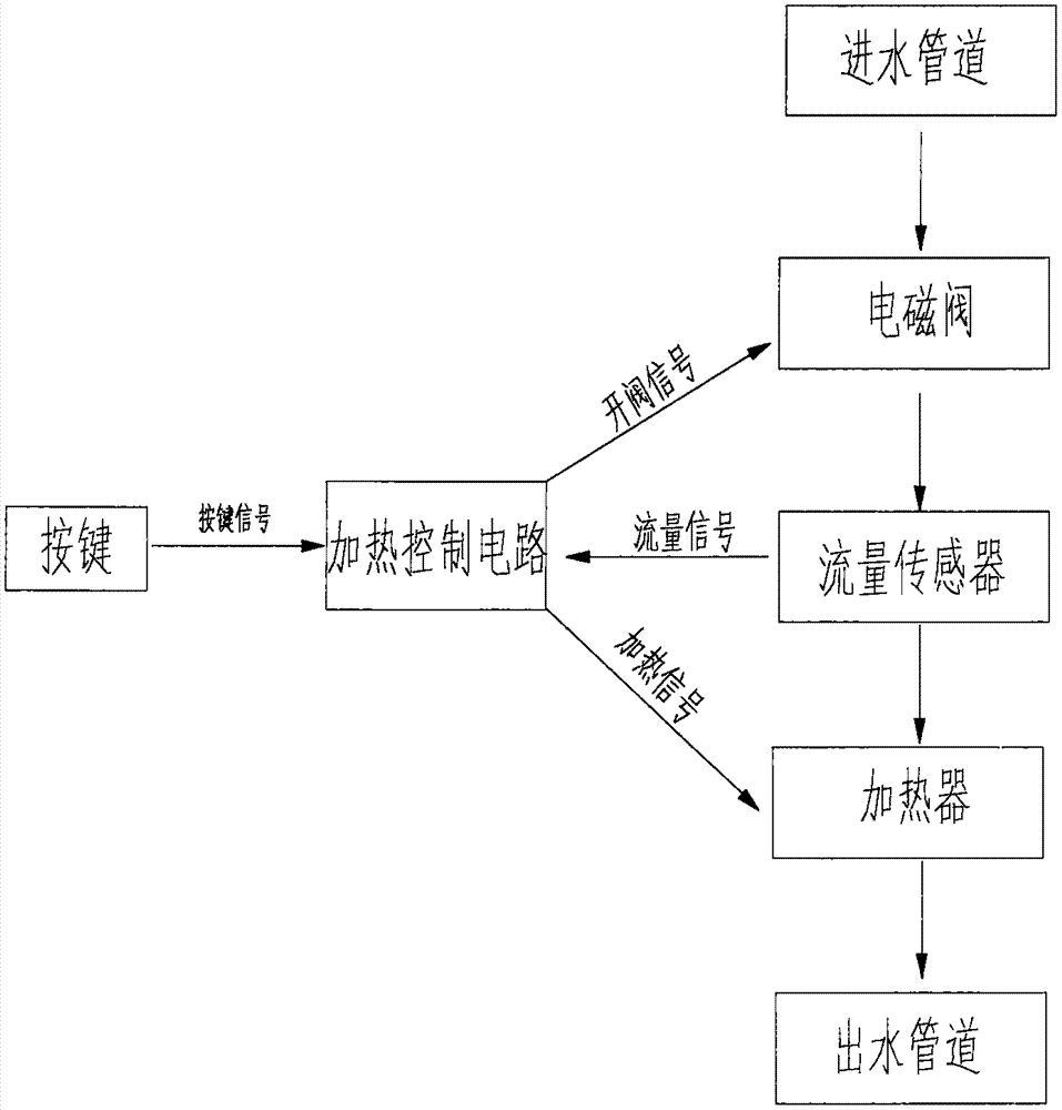
[0020] It should be noted that, in the following examples, using figure 1 The schematic diagram of the present invention describes in detail an energy-saving heating system for water dispensers. When describing the embodiments of the...


PUM


Abstract

The invention discloses an energy-saving type heating system for a water dispenser. The system comprises a key, a heating control circuit, a water inflow pipeline, an electromagnetic valve, a flow sensor, a heater and a water outflow pipeline. The key is connected with the heating control circuit through a circuit, the heating control circuit is connected with the electromagnetic valve, the flow sensor and the heater through electric wires, the water inflow pipeline is connected with the electromagnetic valve, and the water outflow pipeline is connected with the heater. The heater comprises a heating cavity and an electric heating pipe. The electric heating pipe is arranged in the heating cavity, and the electromagnetic valve, the flow sensor and the heater are connected through pipelines. According to the energy-saving type heating system for the water dispenser, the heating power can be automatically adjusted according to the water flow, the constant outflow water temperature can be kept, and the energy saving effect can be achieved. In addition, when currents are small or no current signal is generated, heating is automatically stopped, and the problems of too high water temperature and heating pipe dry burning can be avoided.

Description

technical field [0001] The invention belongs to the field of drinking water equipment, and in particular relates to an energy-saving heating system for drinking water machines. Background technique [0002] At present, the heating system of existing water dispensers mostly adopts a heating system composed of a stainless steel water tank built-in electric heating tube and a mechanical thermostat. Among them, the stainless steel water tank has a built-in electric heating tube as the heating part, and a mechanical thermostat as the heating control part. The principle is that the mechanical thermostat is closely attached to the outer surface of the stainless steel water tank. When the surface temperature of the stainless steel water tank is lower than the operating temperature of the mechanical thermostat, the internal contacts of the thermostat are closed, and the built-in stainless steel water tank is connected. Electric heating tube heating. When the surface temperature of ...

Claims


Application Information

Patent Timeline
Patent Type & Authority Applications(China)
IPC IPC(8): A47J31/56
CPCA47J31/56
Inventor 朱赛刘建丰付勇波
Owner 湖南康之源科技有限公司
Why Eureka
Try Eureka