Rupture disk perforating casing coupling device

A casing coupling and rupture disk technology, applied in the field of oil and gas field development tools, can solve the problems of large influence of oil and gas layers, complex construction procedures, high construction costs and risks, saving tripping time, shortening operation cycle, increasing The effect of job difficulty

Pending Publication Date: 2017-09-05
XI'AN PETROLEUM UNIVERSITY
View PDF9 Cites 2 Cited by
  • Summary
  • Abstract
  • Description
  • Claims
  • Application Information

AI Technical Summary

Problems solved by technology

The conventional perforating operation is to lower the perforating gun into the predetermined layer of the wellbore and then blast the hole, so that the formation fluid enters the wellbore. The construction cost and risk of this operation method are high, and professional construction teams, perforating guns and Hole bombs require professional storage, transportation and maintenance. After perforating, the casing is easy to expand in diameter and casing strength is reduced. After controlling the number of holes and perforating, the effect of flow-limited cluster fracturing is not good, and it also has a great impact on oil and gas layers. ;Hydraulic sandblasting perforation mainly uses high-jet nozzles to spray holes in the target layer to allow formation fluid to enter the wellbore. This operation is much less harmful to the reservoir. However, it still needs to be lowered into special tools first. After the perforation is completed, it is taken out from the underground, the construction process is complicated and the cost is high
Not only that, the number of horizontal wells has increased rapidly in recent years, and it is also difficult to operate in horizontal wells with the current perforation method

Method used


Image

  • Rupture disk perforating casing coupling device
  • Rupture disk perforating casing coupling device
  • Rupture disk perforating casing coupling device

Examples


Embodiment Construction

[0016] The structural principle of the present invention will be discussed in detail below in conjunction with the accompanying drawings.

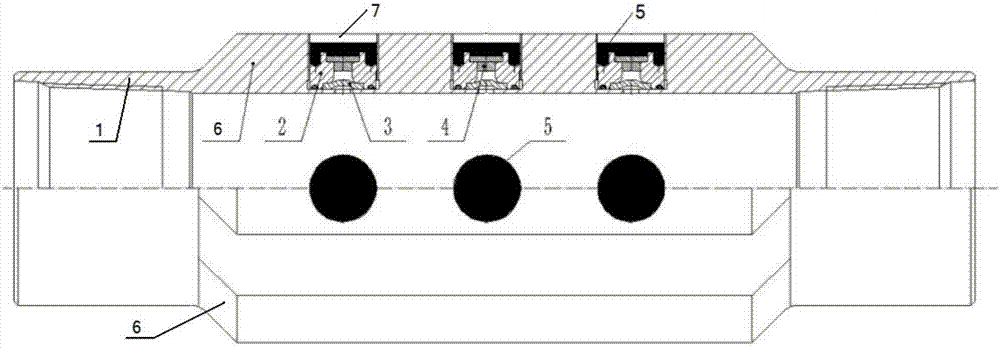
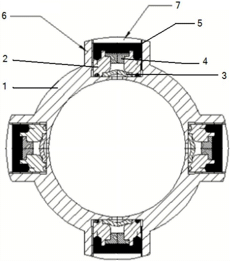
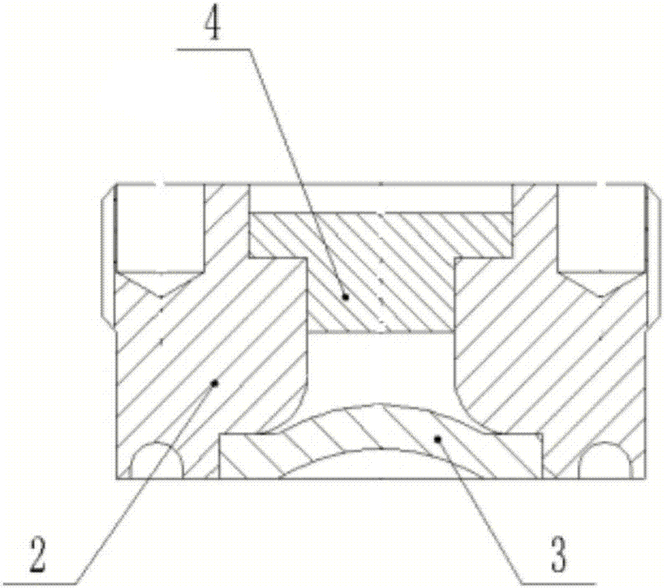
[0017] Such as figure 1 , figure 2 As shown, a rupture disk perforating casing coupling device includes a coupling body 1, on which a protrusion 6 extending in the axial direction is arranged at intervals of 90° in the circumferential direction, and each protrusion There are three openings 7 along the radial direction on the lifter 6, and a nut 2 is arranged inside each opening 7, and a rupture disc 3 is installed between one end of the nut 2 and the bottom surface of the opening 7, and the other end of the nut 2 is installed A pressure cap 4 is provided, and the pressure cap 4 together with the nut 2 and the rupture disc 3 forms a cavity with standard atmospheric pressure (see image 3 ), the upper end of the pressure cap 4 is coated with a self-dissolving softening film 5.

[0018] Working principle of the present invention:

[0019...


PUM


Abstract

The invention discloses a rupture disk perforating casing coupling device and belongs to the field of oil and gas field development tools. The rupture disk perforating casing coupling device comprises a coupling body, wherein bulges which extend along the axial direction are arranged on the coupling body at intervals along the peripheral direction; a plurality of openings along the radial direction are formed in each bulge; a nut is arranged in each opening; a rapture disk is arranged between one end of each nut and the bottom surface of the corresponding opening, a pressing cap is arranged at the other end of the nut, a cavity with certain air pressure is formed by the pressing cap, the nut and the rapture disk; and a self-dissolved softening membrane coats the upper end of each pressing cap. Perforating and fracturing are carried out by adopting the rupture disk perforating casing coupling device, the structural force of a connected casing is not destroyed, special perforating tool and constructor are not needed, ball seat drilling operation is not needed, the perforation difficulty of a horizontal well can be reduced, an opportunity can be freely selected to control perforating, convenient operation means are provided for testing and controlling mining, meanwhile, the construction cost is greatly reduced and the construction period is shortened.

Description

technical field [0001] The invention belongs to the field of oil and gas field development tools, and in particular relates to a rupture disk perforating casing coupling device. Background technique [0002] Fracturing is one of the main production stimulation measures in the exploration and development of oil and gas fields, and perforation is an important link before fracturing. At present, there are two types of perforation operations: conventional perforation and hydraulic sandblasting perforation. The conventional perforating operation is to lower the perforating gun into the predetermined layer of the wellbore and then blast the hole, so that the formation fluid enters the wellbore. The construction cost and risk of this operation method are high, and professional construction teams, perforating guns and Hole bombs require professional storage, transportation and maintenance. After perforating, the casing is easy to expand in diameter and casing strength is reduced. Af...

Claims


Application Information

Patent Timeline
Patent Type & Authority Applications(China)
IPC IPC(8): E21B43/11E21B17/08
CPCE21B17/08E21B43/11E21B34/063E21B43/114E21B43/119
Inventor 周德胜杨华
Owner XI'AN PETROLEUM UNIVERSITY
Why Eureka
Try Eureka