

Rapid 3D blood vessel boundary segmenting method and system
A blood vessel and boundary technology, applied in the fields of medical detection and medical image processing, can solve problems such as instability, low efficiency of manual segmentation, and inability to rule out lumen branches
- Summary
- Abstract
- Description
- Claims
- Application Information
AI Technical Summary
Problems solved by technology
Method used
Image

Examples
Embodiment 1
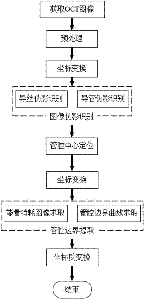
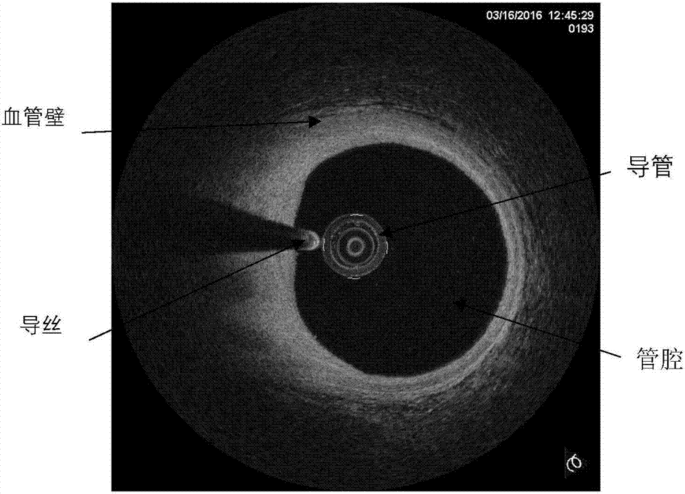
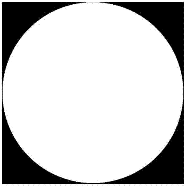
[0098] Such as figure 1 , is a flow chart of the fast three-dimensional segmentation method for blood vessel boundaries implemented in the present invention. Firstly, the original OCT image is obtained and preprocessed. The preprocessing includes filtering and denoising and using a fixed mask to remove useless information in the periphery of the image. Then, the image was transformed into polar coordinates, and the guide wire and catheter artifacts in the original OCT image were removed according to the obtained image. Then, the lumen center in the original OCT image is found by using the fast wavefront diffusion algorithm. Then the polar coordinate transformation is carried out according to the obtained lumen center, and the lumen boundary is quickly extracted by the method of dynamic programming. Finally, the extracted boundary curve in the polar coordinate system is inversely transformed back to the boundary curve in the OCT original image coordinate system.
[0099] Com...
Embodiment 2
[0182] Below, combine Figure 9 , the fast three-dimensional segmentation system of the blood vessel boundary in this embodiment will be described. The system includes:
[0183] A preprocessing module, which preprocesses the acquired image;
[0184] Coordinate transformation module 1 takes the center of the image as the origin of polar coordinates, and converts the image into an image in the polar coordinate system;
[0185] Image artifact removal module: determine the artifacts in the image, and remove the artifacts from the image transformed into the polar coordinate system after determining the center of the lumen; the artifacts include catheter and guide wire artifacts;
[0186] Lumen center positioning module: determine the center of the vessel lumen in the original image;
[0187] Coordinate transformation module 2: convert the image of the determined center of the lumen of the blood vessel into an image in the polar coordinate system with the center of the lumen as t...
PUM
 Abstract
Description
Claims
Application Information