Camera calibrating method and system in vehicle panoramic looking-around system

A panoramic surround view and calibration method technology, applied in the field of assisted driving equipment calibration, can solve problems such as installation error angle error, affecting 360-degree surround view splicing effect, camera parameter error, etc., to ensure accuracy, facilitate mass production line deployment, The effect of high degree of automation

Active Publication Date: 2017-09-05
IFLYTEK CO LTD
View PDF4 Cites 32 Cited by
  • Summary
  • Abstract
  • Description
  • Claims
  • Application Information

AI Technical Summary

Problems solved by technology

Although this method improves the calibration efficiency to a certain extent, due to the existence of installation errors (such as position errors, angle errors, etc.), directly adapting the camera

Method used


Image

  • Camera calibrating method and system in vehicle panoramic looking-around system
  • Camera calibrating method and system in vehicle panoramic looking-around system
  • Camera calibrating method and system in vehicle panoramic looking-around system

Examples


example 1

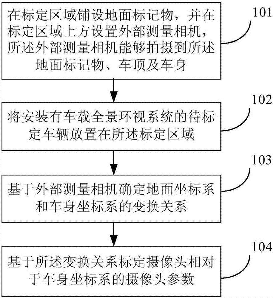
[0175] Example 1: The calibration reference object is set on the roof of the vehicle to be calibrated. Correspondingly, the second calibration unit may include the following subunits:

[0176] A calibration reference object image acquisition subunit, configured to acquire an image of the calibration reference object captured by an external measurement camera;

[0177] The first coordinate determination subunit is used to determine the pixel point coordinates of each corner point on the calibration reference object and the physical coordinates of the roof, and determine the position of each corner point on the vehicle body according to the roof physical coordinates of each corner point on the calibration reference object. coordinates in the coordinate system;

[0178] The first parameter calibration subunit is used to calibrate the camera parameters of the external measurement camera relative to the vehicle body coordinate system by using the pixel coordinates of each corner po...

example 2

[0179] Example 2: The calibration reference object is set to be the projection of the body of the vehicle to be calibrated on the ground coordinate system. Correspondingly, the second calibration unit may include the following subunits:

[0180] The body photo acquisition subunit is used to obtain the whole body photo taken by the external measurement camera;

[0181] The calculation subunit is used to calculate the pixel point coordinates of the four projected points in the ground coordinate system around the body in the external measurement camera;

[0182] The second coordinate determination subunit determines the coordinates of four projected points on the ground coordinate system around the vehicle body in the vehicle body coordinate system;

[0183] The second parameter calibration subunit is used to calibrate the coordinates of the external measurement camera relative to the vehicle body according to the pixel coordinates of the four projected points around the vehicle ...


PUM


Abstract

The invention discloses a camera calibrating method and system in a vehicle panoramic looking-around system. The method comprises that a ground tag is laid in a calibration area, and an external measuring camera which can shoot the ground tag, a roof and a vehicle body is arranged over the calibration area; a to-be-calibrated vehicle with the vehicle panoramic looking-around system is arranged in the calibration area; the transformation relation between a ground coordinate system and a vehicle body coordinate system is determined on the basis of the external measuring camera; and a camera parameter of the camera relative to the vehicle body coordinate system is calibrated on the basis of the transformation relation. Via the calibrating method and system, the calibrating efficiency can be improved, and the accuracy of a calibration result is ensured.

Description

technical field [0001] The invention relates to the field of calibration of auxiliary driving equipment, in particular to a camera calibration method and calibration system in a vehicle-mounted panoramic surround view system. Background technique [0002] Usually, drivers can only rely on the help of rearview mirrors or reversing images in scenarios such as starting and parking. However, due to the presence of obstacles such as the front of the car, windows, pillars, and the driver's own limited field of vision, there is a blind spot in the driver's field of vision, and it is impossible to judge whether there are obstacles in the blocked area and the distance between obstacles, which is very difficult for the driver to park in the parking lot , Starting, and driving safety in urban congested roads, narrow streets and other scenarios constitute a great obstacle. [0003] In order to avoid the impact of blind spots on vehicle driving safety, in recent years, the visual assist...

Claims


Application Information

Patent Timeline
IPC IPC(8): G06T7/80
CPCG06T7/80
Inventor 张敬刘聪王智国胡国平郭涛谢信珍雷琴辉
Owner IFLYTEK CO LTD
Why Eureka
Try Eureka