Card tray structure and electronic device

A technology for electronic equipment and card trays, which is applied in circuits, electrical components, transmission systems, etc., and can solve the problems of easy loosening of cards and difficulty in loading cards.

Inactive Publication Date: 2017-09-05
QIKU INTERNET TECH SHENZHEN CO LTD
View PDF4 Cites 1 Cited by
  • Summary
  • Abstract
  • Description
  • Claims
  • Application Information

AI Technical Summary

Problems solved by technology

[0006] The purpose of the present invention is to provide an electronic device, which aims to solve the technical problems that the existing electronic device is difficult to load into the card and the card is easy to get loose

Method used


Image

  • Card tray structure and electronic device
  • Card tray structure and electronic device
  • Card tray structure and electronic device

Examples


Embodiment Construction

[0031] Exemplary embodiments of the present disclosure will be described in more detail below with reference to the accompanying drawings. Although exemplary embodiments of the present disclosure are shown in the drawings, it should be understood that the present disclosure may be embodied in various forms and should not be limited by the embodiments set forth herein. Rather, these embodiments are provided for more thorough understanding of the present disclosure and to fully convey the scope of the present disclosure to those skilled in the art.

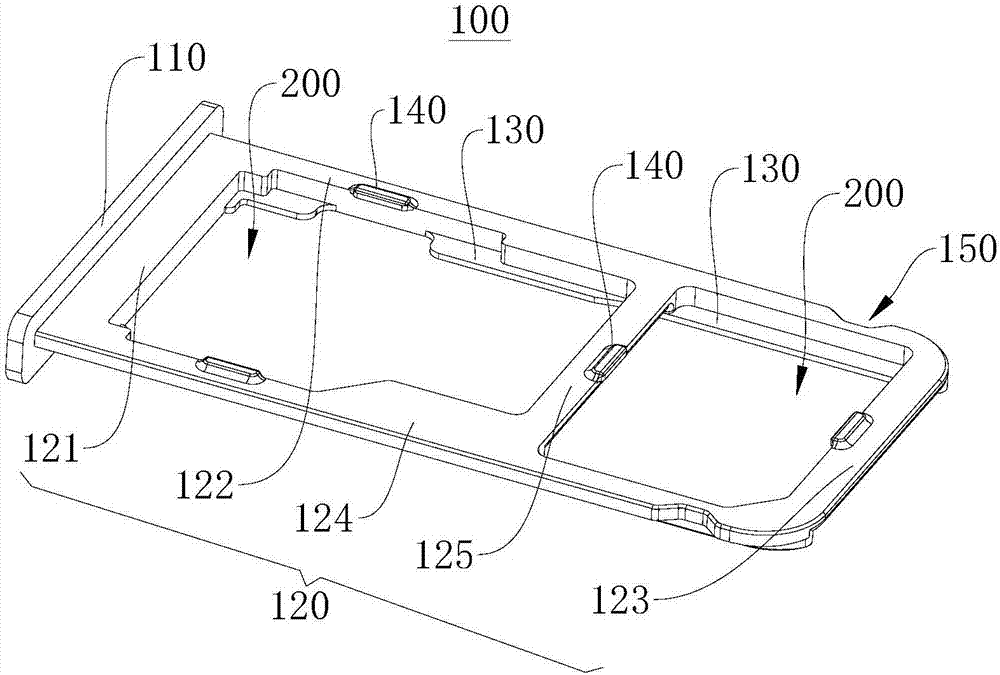
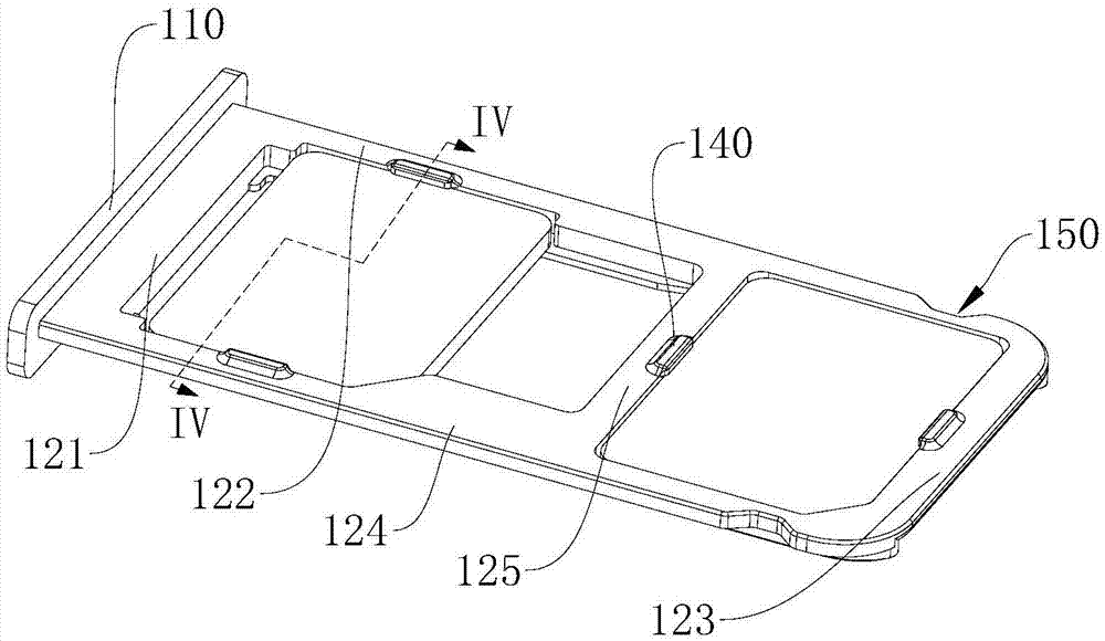
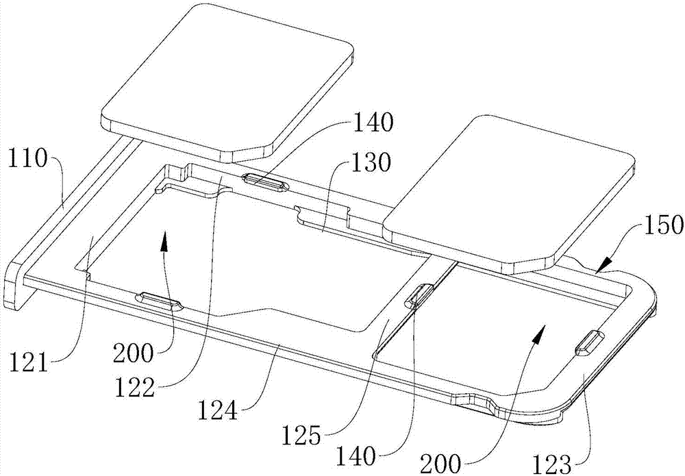
[0032] see figure 1 , figure 1 It shows a structural schematic view of the card holder structure 100 according to an embodiment of the present invention. It should be noted that the reference numerals with arrows in all the drawings refer to virtual structures, such as holes, grooves, cavities, etc., without Arrow reference numbers refer to physical structures.

[0033] An embodiment of the present invention provides a card holde...


PUM


Abstract

The invention provides a card tray structure and electronic equipment, and relates to the technical field of electronic equipment. The card holder structure 100 is used in electronic equipment, and the card holder structure 100 includes a card holder door plate 110 , a card limiting plate 120 , a card bearing portion 130 and a card buckle 140 . One end of the card limiting plate 120 is connected to the card tray door 110 , and at least one card placement position 200 matching the shape of the card is opened through the card limiting plate 120 . The card bearing part 130 is arranged on the card placement position 200 and is located at one side of the card placement position 200, and the card bearing part 130 is used to prevent the card from falling. The card buckle 140 is disposed on the card placement position 200 and is located on the other side of the card placement position 200 opposite to the card bearing portion 130 , and the card buckle 140 and the card bearing portion 130 are used to clamp on both sides of the card. The card is clamped between the card buckle 140 and the card bearing part 130 , so that the card cannot move freely in the thickness direction and prevents the card from accidentally falling off the card limiting plate 120 .

Description

technical field [0001] The invention relates to the technical field of electronic equipment, in particular to a card holder structure and electronic equipment. Background technique [0002] With the development of smart phone technology, more and more smart phones adopt the design of metal frame and non-detachable back cover. [0003] A smart phone with a metal frame and a non-detachable back cover usually needs to set a gap on the metal frame, and insert cards such as SIM (Subscriber Identity Module, customer identification module) card or mobile phone memory card into the phone through the gap by means of a card tray. body. [0004] After the existing card tray carries the card, due to the small size and light weight of the card, the card is very easy to slip off the card tray, making it difficult for the user to insert the card into the fuselage with the card tray, even after inserting the card into the fuselage with the card tray , It is also easy for the card to loose...

Claims


Application Information

Patent Timeline
Patent Type & Authority Applications(China)
IPC IPC(8): H01R13/502H01R13/639H04B1/3816
CPCH01R13/502H01R13/639H04B1/3816
Inventor 黄少锋
Owner QIKU INTERNET TECH SHENZHEN CO LTD
Why Eureka
Try Eureka