A device and method for driving plate hole turning and forming by using multi-directional magnetic field force

A magnetic field force and plate technology, applied in forming tools, metal processing equipment, manufacturing tools, etc., can solve problems such as wrinkling of sheet flanges, avoid cracks, improve plastic fluidity, and improve flanging performance.

Active Publication Date: 2019-03-12
CENT SOUTH UNIV
View PDF7 Cites 0 Cited by
  • Summary
  • Abstract
  • Description
  • Claims
  • Application Information

AI Technical Summary

Problems solved by technology

However, when the blank holder force is small, the sheet flange will wrinkle

Method used


Image

  • A device and method for driving plate hole turning and forming by using multi-directional magnetic field force
  • A device and method for driving plate hole turning and forming by using multi-directional magnetic field force
  • A device and method for driving plate hole turning and forming by using multi-directional magnetic field force

Examples


Embodiment 1

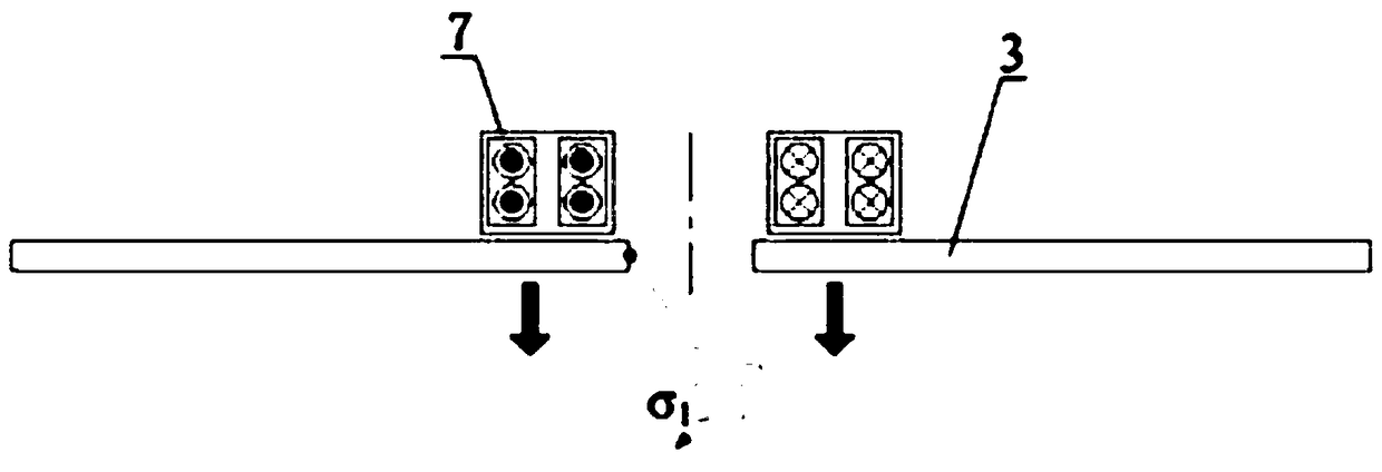
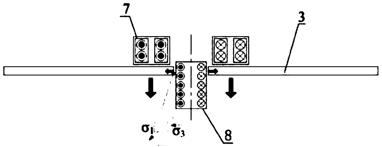
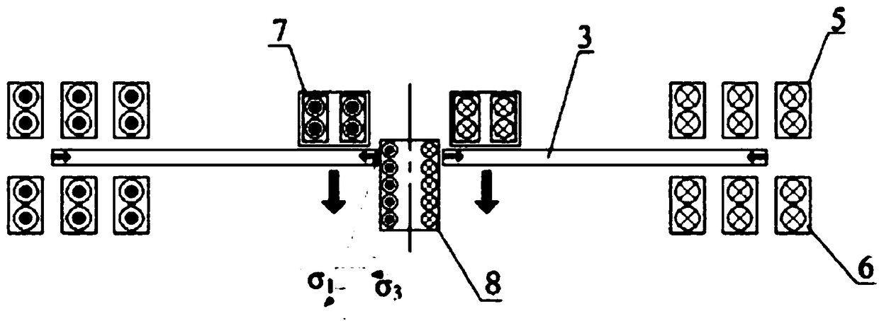
[0047] Such as Figure 4 with Figure 5 As shown, a device of the present invention that utilizes multi-directional magnetic force to drive plate hole turning and forming, the device includes a blank holder 1 and a die 2, and the blank holder 1 is placed above the die 2. The blank holder 1 is used to press the plate 3 to be formed by turning holes between the blank holder 1 and the die 2 . The die 2 has a die cavity 4 inside. On the blank holder 1 and the die 2, an upper coil groove and a lower coil groove are respectively arranged oppositely, and an upper-end reducing coil 5 is embedded in the upper coil groove, and a lower end coil 5 is embedded in the lower coil groove. Part of the reduced diameter coil 6. A prefabricated hole is opened on the plate 3, an axial drawing coil 7 is arranged above the edge of the prefabricated hole of the plate 3, and an internal bulging coil 8 is arranged in the prefabricated hole of the plate 3. The internal bulging coil 8 comprises verti...

Embodiment 2

[0052] Such as Figure 6 to Figure 9 As shown, a device of the present invention that utilizes multi-directional magnetic force to drive plate hole turning and forming, the device includes a blank holder 1 and a die 2, and the blank holder 1 is placed above the die 2. The blank holder 1 is used to press the plate 3 to be formed by turning holes between the blank holder 1 and the die 2 . The die 2 has a die cavity 4 inside. On the blank holder 1 and the die 2, an upper coil groove and a lower coil groove are respectively arranged oppositely, and an upper-end reducing coil 5 is embedded in the upper coil groove, and a lower end coil 5 is embedded in the lower coil groove. Part of the reduced diameter coil 6. A prefabricated hole is opened on the plate 3, an axial drawing coil 7 is arranged above the edge of the prefabricated hole of the plate 3, and an internal bulging coil 8 is arranged in the prefabricated hole of the plate 3. Die 2 is placed on a base plate 9, and base pla...


PUM


Abstract

The invention discloses a device and method for driving plate hole flanging forming through multidirectional magnetic field force. The device comprises a blank holder (1) and a concave die (2). The blank holder (1) is arranged above the concave die (2) and used for pressing a plate (3) to be subjected to hole flanging forming between the blank holder (1) and the concave die (2). A concave die cavity (4) is formed in the concave die (2). An upper coil groove and a lower coil groove are correspondingly formed in the blank holder (1) and the concave die (2). Upper end hole shrinkage coils (5) are embedded in the upper coil groove. Lower end hole shrinkage coils (6) are embedded in the lower coil groove. Axial deep drawing coils (7) are arranged above the edge of a pre-formed hole of the plate (3). An inner bulging coil (8) is arranged in the pre-formed hole of the plate (3). According to the device and method, cracks can be prevented from being generated to a round hole flanging deformation area during hole flanging forming, the product quality is good, and the forming process is simple.

Description

technical field [0001] The invention relates to the technical field of material processing and forming, and in particular to a device and method for driving plate hole turning and forming by using multidirectional magnetic field force. Background technique [0002] The traditional hole turning forming method is to turn the hole directly with a steel mold. This method requires a set of large forming tooling with convex and concave molds and a large table press, and the production cost is high and the cycle is long. When the flanging coefficient is small, cracks are likely to occur in the flanging deformation area of ​​the round hole, which usually requires multiple forming processes. Grinding, trimming, and annealing are required in the middle of the process. The manufacturing process is quite complicated, resulting in low production efficiency and high scrap rate. High, high cost, and labor-intensive workers. [0003] Electromagnetic pulse forming is a method of high-speed ...

Claims


Application Information

Patent Timeline
Patent Type & Authority Patents(China)
IPC IPC(8): B21D26/14B21D37/10
CPCB21D26/14B21D37/10
Inventor 崔晓辉喻海良王青山
Owner CENT SOUTH UNIV
Why Eureka
Try Eureka