
Automatic nut burying and sprue cutting equipment

A technology for cutting gates and nuts, applied in the field of machinery, can solve the problems of low production efficiency, reduced product quality, and high production costs, and achieve the effects of high production efficiency and high degree of automation

Active Publication Date: 2017-09-08
YONGGAO CO LTD
View PDF5 Cites 4 Cited by
  • Summary
  • Abstract
  • Description
  • Claims
  • Application Information

AI Technical Summary

Problems solved by technology

[0003] The injection molding machine feeds thermoplastic or thermosetting plastic into the mold through the gate. When the plastic product is formed in the mold, the thermoplastic or thermosetting plastic at the gate will also solidify, and after solidification, it will be connected with the plastic product. When the plastic When the product is a pipe clip, it is often necessary to embed the nut. People need to deburr the nut first, and then embed the nut into the pipe clip. The deburring and burying of the existing nut are manually operated, and the operation efficiency is low. ; Moreover, in order to obtain plastic products, the gate needs to be cut off. The existing gate cutting method is usually to manually cut the gate by the operator, and manual cutting of the gate requires a lot of manpower and material resources, and the production cost is high. , manual gate cutting is affected by the proficiency and fatigue of operators, and the production efficiency is low. Moreover, there are problems such as uneven incision or even wrong cutting of plastic products, resulting in a decrease in product quality.

Method used


Image

  • Automatic nut burying and sprue cutting equipment
  • Automatic nut burying and sprue cutting equipment
  • Automatic nut burying and sprue cutting equipment

Examples


Embodiment Construction

[0029] The following are specific embodiments of the present invention and in conjunction with the accompanying drawings, the technical solutions of the present invention are further described, but the present invention is not limited to these embodiments.

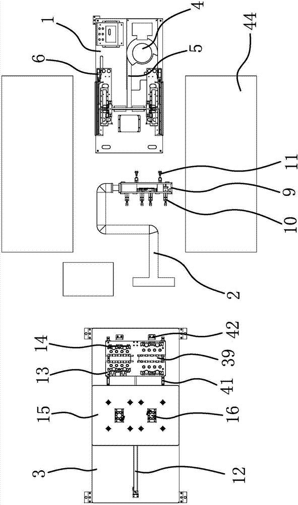
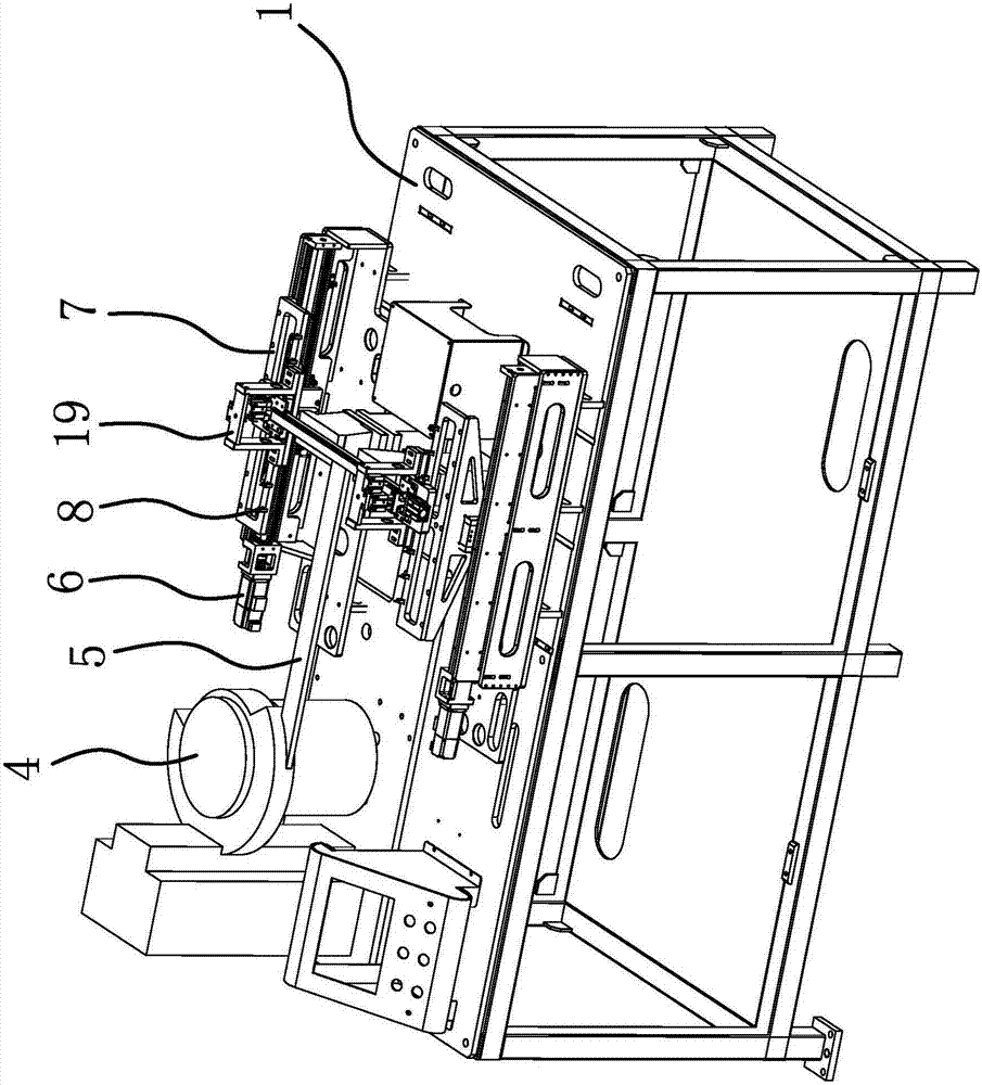
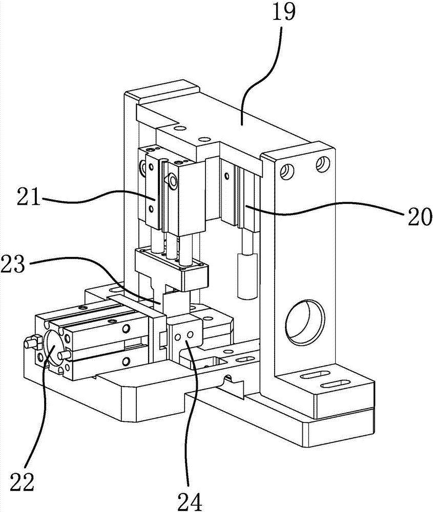
[0030] This automatic buried nut and gate cutting equipment is mainly used for buried nuts and gate cutting for pipe clamps. Such as figure 1 As shown, the automatic buried nut and gate cutting equipment includes a first workbench 1, a manipulator 2, a second workbench 3, a vibrating tray 4, a conveying channel 5, a first driving source 6, a sliding frame 7, and a positioning column 8 , mounting plate 9, first clamping cylinder 10, clamping air nozzle 11, second drive source 12, slide plate 13, positioning frame 14, mounting frame 15, lifting cylinder 16, first platen 17 and cutter 18.

[0031] Such as figure 2 As shown, the vibrating tray 4 and the conveying channel 5 are all fixedly connected on the first workbench 1,...


PUM


Abstract

The invention belongs to the technical field of machines, and provides automatic nut burying and sprue cutting equipment which solves the problem that an existing pipe clamp is low nut burying and sprue cutting efficiency. The automatic nut burying and sprue cutting equipment is characterized in that a first driving source on a first workbench can drive a sliding rack to move; locating columns are arranged on the sliding rack in a spaced manner; the feed end of a conveying passage is connected with a vibrating material disc; the discharge end of the conveying passage is located at the locating columns; a manipulator is fixedly connected with a mounting plate; first clamping cylinders are arranged on one side of the mounting plate; clamping air nozzles are formed in the other side of the mounting plate; a second driving source and a sliding plate are arranged on a second workbench; the second driving source can drive the sliding plate to move; a locating rack is arranged on the sliding plate; a mounting rack is arranged on the second workbench; lifting air cylinders are arranged on the mounting rack; piston rods of the lifting air cylinders are fixedly connected with a first pressing plate; and the first pressing plate is fixedly connected with cutters. The automatic nut burying and sprue cutting equipment has the advantage of improving the production efficiency of a pipe clamp.

Description

technical field [0001] The invention belongs to the technical field of machinery, and relates to an automatic nut-burying and gate-cutting device. Background technique [0002] Injection molding is a method of producing shapes for industrial products. Products usually use rubber injection molding and plastic injection molding. Injection molding machine is the main molding equipment for making thermoplastics or thermosetting plastics into various shapes of plastic products using plastic molding molds. Injection molding is realized through injection molding machines and molds. [0003] The injection molding machine feeds thermoplastic or thermosetting plastic into the mold through the gate. When the plastic product is formed in the mold, the thermoplastic or thermosetting plastic at the gate will also solidify, and after solidification, it will be connected with the plastic product. When the plastic When the product is a pipe clip, it is often necessary to embed the nut. Peo...

Claims


Application Information

Patent Timeline
IPC IPC(8): B29C45/14B29C45/42B29C45/38
CPCB29C45/14008B29C45/14065B29C45/382B29C45/4225B29C2045/14868
Inventor 张建均张云飞金龙张慧徐双金瑶
Owner YONGGAO CO LTD
Learn More