Supercharge Your Innovation With Domain-Expert AI Agents!

Rotor head of centrifugal waving flapping hinge

A technology of waving hinges and rotor heads, applied in the field of unmanned aerial vehicles, can solve the problems of loss of kinetic energy, cumbersomeness, and unsuitability for unmanned aerial vehicles

Active Publication Date: 2017-09-08
郑可为
View PDF12 Cites 6 Cited by
  • Summary
  • Abstract
  • Description
  • Claims
  • Application Information

AI Technical Summary

Problems solved by technology

Ordinary pendulum oscillators are complex and bulky, and are not suitable for use on drones
When the blades of the multi-rotor UAV rotate, because the linear velocity of the outer periphery of the blade is higher than the linear velocity of the inner periphery, the lift force on the outer periphery of the blade is larger, so the blade is affected by centrifugal force and lift force when rotating, and the blade will Into an upward state, resulting in reduced propeller efficiency, loss of kinetic energy, and reduced aircraft stability

Method used


Image

  • Rotor head of centrifugal waving flapping hinge
  • Rotor head of centrifugal waving flapping hinge
  • Rotor head of centrifugal waving flapping hinge

Examples


Embodiment Construction

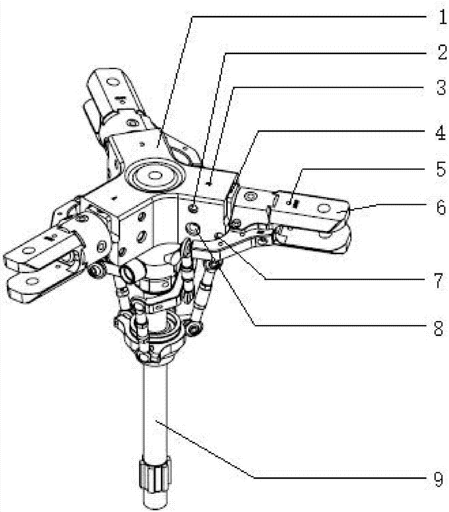
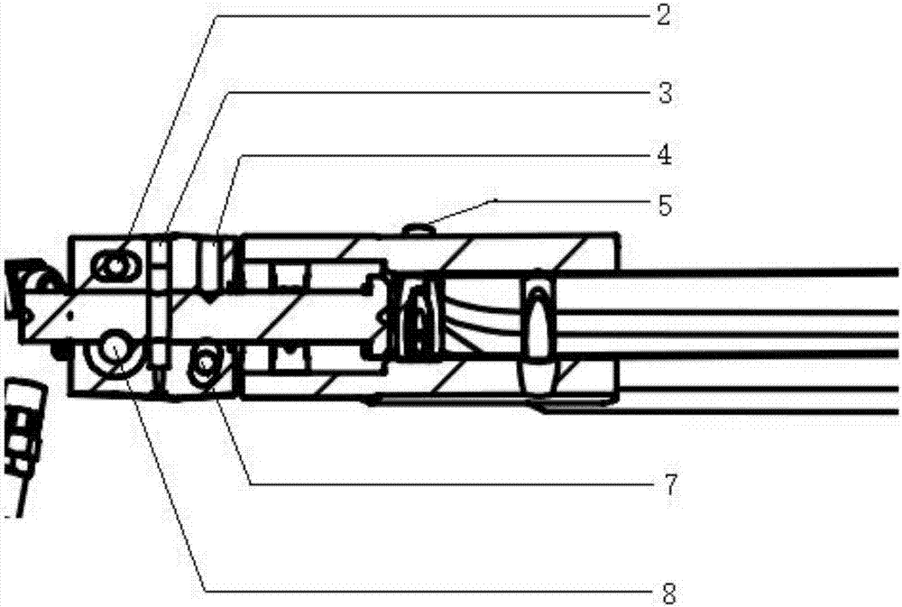
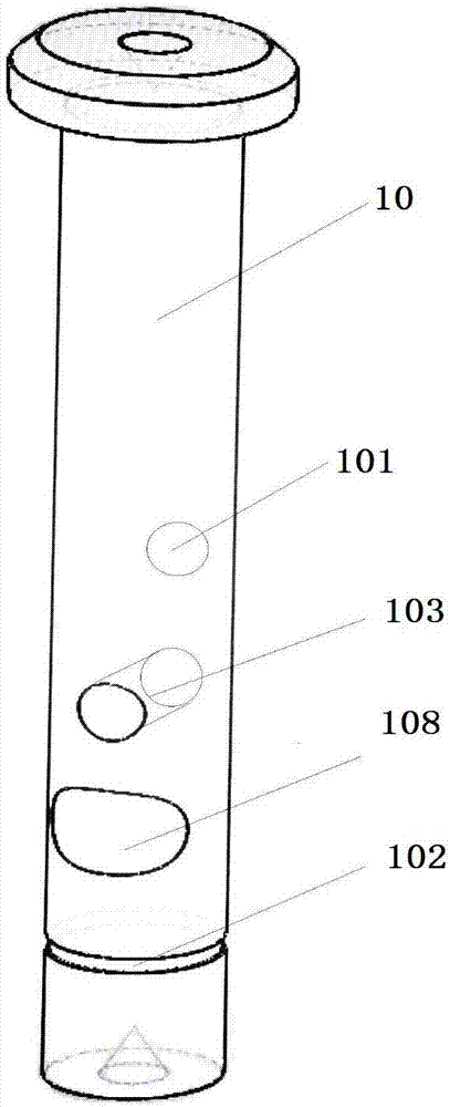
[0021] figure 1 A structural schematic diagram of a centrifugal swinging hinged rotor head according to an embodiment of the present invention. Such as figure 1 As shown, a kind of centrifugal swinging hinged rotor head provided by the present invention comprises rotor central axis 9, middle joint 1, swinging hinge 8, and transverse shaft 10 connected sequentially from inside to outside (in image 3 shown in ), swing hinge 5, paddle clamp 6; the swing hinge 8 and the paddle clamp 6 are connected by the horizontal shaft 10 arranged in the middle joint 1, and the paddle clamp 6 is connected with To install the paddle 12 (in Figure 4 shown in ), the pendulum hinge 5 is arranged between the oar clip 6 and the blade 12, the middle joint 1 defines the movable angle of the swing hinge 8, and the blade 12 rotates with the The swinging hinges 8 are on the same axis line, and the axis line where it is located is the axial direction of the rotor central axis 9 . The central axis of ...


PUM


Abstract

The invention provides a rotor head of a centrifugal waving flapping hinge and belongs to the technical field of unmanned aerial vehicles. The rotor head comprises a rotor wing central shaft, a central connector, a flapping hinge, a cross shaft, a shimmy hinge and a propeller clamp. The flapping hinge and the shimmy hinge are connected through the cross shaft arranged in the central connector; the propeller clamp is used for mounting a propeller; the shimmy hinge is arranged between the propeller clamp and the propeller; the central connector defines the moving angle of the flapping hinge; the propeller rotates to be in the same axial lead of the flapping hinge; and the central shaft of the flapping hinge is below the axial lead, around which the propeller rotates. The rotor head of the centrifugal waving flapping hinge provided by the invention is provided with a novel flapping hinge structure, so that a downward force is provided for the propeller when the propeller rotates, the lift-up angle of the propeller is reduced, the propeller efficiency is increased, and therefore, the stability of an airplane is increased.

Description

technical field [0001] The invention relates to the technical field of unmanned aerial vehicles, in particular to a centrifugal flapping hinged rotor head. Background technique [0002] A multi-rotor UAV is a special unmanned helicopter with three or more rotor shafts. It is rotated by an electric motor on each shaft to drive the rotor, thereby generating thrust. The collective pitch of the rotors is fixed, not variable like normal helicopters. By changing the relative rotational speed between different rotors, the size of the single-axis propulsion can be changed, thereby controlling the trajectory of the aircraft. [0003] Most of the existing multi-rotor UAVs only have variable-pitch hinges and shimmy hinges, and seldom use the waving hinge design. The vibration of the aircraft during flight is relatively large, and the fuselage of the aircraft responds greatly to slight changes in attitude. Ordinary pendulum oscillators are complex and bulky, and are not suitable for...

Claims


Application Information

Patent Timeline
Patent Type & Authority Applications(China)
IPC IPC(8): B64C27/37
CPCB64C27/37
Inventor 郑锋吴立苏正
Owner 郑可为
Features
  • R&D
  • Intellectual Property
  • Life Sciences
  • Materials
  • Tech Scout
  • Unparalleled Data Quality
  • Higher Quality Content
  • 60% Fewer Hallucinations
Learn More