Delivery mechanism and conveying device

A technology of conveying mechanism and conveying device, which is applied in the direction of conveyor, transportation and packaging to achieve the effect of reducing energy consumption, reducing rigidity and reducing energy loss.

Pending Publication Date: 2017-09-08
江苏丰东热技术有限公司
View PDF12 Cites 2 Cited by
  • Summary
  • Abstract
  • Description
  • Claims
  • Application Information

AI Technical Summary

Problems solved by technology

[0004] The present invention provides a transmission mechanism and a conveying device, aimin

Method used


Image

  • Delivery mechanism and conveying device
  • Delivery mechanism and conveying device
  • Delivery mechanism and conveying device

Examples


Embodiment 1

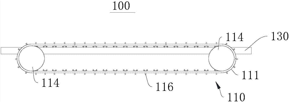
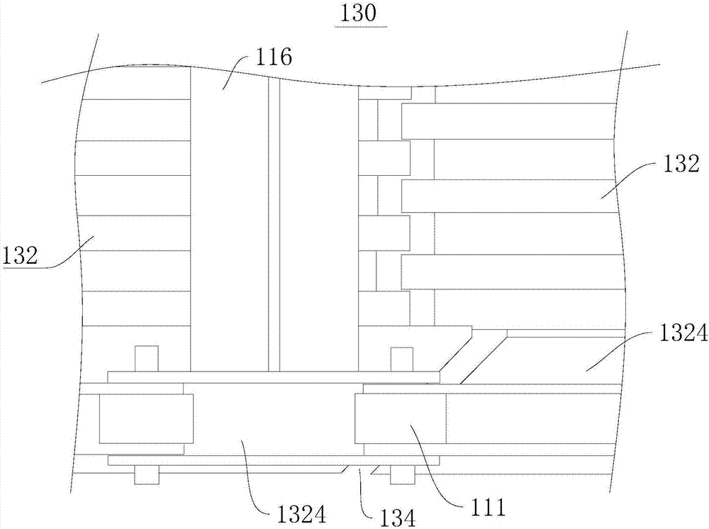
[0031] This embodiment provides a delivery device 100, please refer to figure 1 , this conveying device 100 includes a conveying mechanism 110 and a carrying plate 130 .

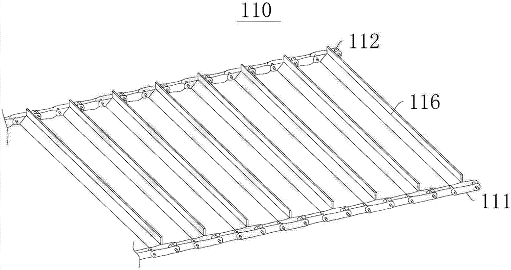
[0032] see figure 1 and figure 2 , the transmission mechanism 110 includes a first connecting part 111 , a second connecting part 112 , a driving part 114 and a plurality of pushing parts 116 .

[0033] Specifically, the first connecting part 111 and the second connecting part 112 are configured as chains, and the driving part 114 is a sprocket. The first connecting parts 111 are connected end to end to form a closed structure, and the second connecting parts 112 are connected end to end to form a closed structure.

[0034] There are two groups of driving parts 114, and each group of driving parts 114 includes a driving sprocket and a driven sprocket. The two sets of active components 114 cooperate with the first connecting component 111 and the second connecting component 112 respectively. The active ...

Embodiment 2

[0056] The structure of the conveying device 100 provided by the embodiment of the present invention is basically the same as that of the conveying device 100 in the first embodiment, the difference lies in that the raceway 1322 on the bearing unit 132 is formed differently.

[0057] see Figure 5 , in this embodiment, the carrying unit 132 includes a base plate 1325 and a plurality of limiting rods 1326 . The limiting rod 1326 is disposed on the base plate 1325 and fixedly connected with the base plate 1325 . The extending direction of the limiting plate is consistent with the extending direction of the first connecting member 111 .

[0058] A raceway 1322 is formed between two adjacent limiting rods 1326 .

[0059] Counting from the first connecting member 111 to the second connecting member 112, the odd-numbered raceways 1322 and the even-numbered raceways 1322 are alternately distributed in the length direction of the first connecting member 111, so that both ends of the...


PUM


Abstract

The invention provides a delivery mechanism and a conveying device, and belongs to the field of metallurgical engineering. The delivery mechanism comprises a first connection element, a second connection element, a drive element and a plurality of push elements, wherein the head and the tail of the first connection element are connected to form a closed structure, the head and the tail of the second connection element are connected to form a closed structure, and the first connection element and the second connection element are oppositely arranged; the plurality of push elements are erected between the first connection element and the second connection element, and an accommodating space is formed between each two adjacent push elements; and the drive element is matched with the first connection element and/or the second connection element. The conveying device comprises a bearing plate and the delivery mechanism. The delivery mechanism and the conveying device can reduce energy consumption while improving the capacity.

Description

technical field [0001] The invention relates to the field of metallurgical engineering, in particular to a transmission mechanism and a conveying device. Background technique [0002] In the production process of wear-resistant steel balls, it is necessary to anneal the wear-resistant steel balls. The existing processing method is that the steel balls are placed on the metal conveyor belt, the steel balls are transported to the annealing furnace by the metal conveyor belt, and then transported out from the annealing furnace. [0003] The mass of steel balls is relatively large, while the rigidity of the metal conveyor belt is poor, so the existing metal conveyor belt cannot load a large number of steel balls at the same time, resulting in small capacity and low production efficiency. Contents of the invention [0004] The present invention provides a transmission mechanism and a conveying device, aiming at solving the above-mentioned problems existing in the metal conveyo...

Claims


Application Information

Patent Timeline
IPC IPC(8): B65G17/06
CPCB65G17/067
Inventor 王海燕刘建华沈顺飞顾剑峰
Owner 江苏丰东热技术有限公司
Why Eureka
Try Eureka