Elevator power failure emergency device and system

An emergency device and elevator technology, applied in the field of elevators, can solve problems such as passengers being trapped and unable to play an emergency role, and achieve the effect of improving reliability

Active Publication Date: 2017-09-08
HITACHI BUILDING TECH GUANGZHOU CO LTD
View PDF4 Cites 8 Cited by
  • Summary
  • Abstract
  • Description
  • Claims
  • Application Information

AI Technical Summary

Problems solved by technology

In the prior art, the maintenance method for the energy storage device is that the staff regularly maintain and maintain the elevator energy storage device. The disadvantage of this is that if the energy storage device fails during the maintenance interval, when the power grid fails, it cannot It plays an emergency role and may easily cause passengers to be trapped

Method used


Image

  • Elevator power failure emergency device and system
  • Elevator power failure emergency device and system
  • Elevator power failure emergency device and system

Examples


Embodiment 1

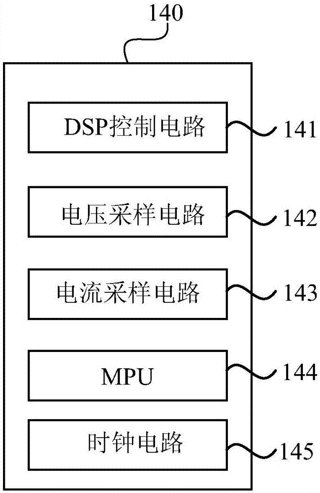
[0036] figure 1 It is a structural schematic diagram of an elevator power failure emergency device provided by Embodiment 1 of the present invention. This device can be used to provide emergency power supply to the elevator after the mains power failure, such as figure 1 As shown, the device includes: a switching unit 110 , a charging emergency unit 120 , a battery detection unit 130 , a detection control unit 140 and a communication unit 150 .

[0037] The input end of the switching unit 110 is connected to the mains grid, and the output end of the switching unit 110 is connected to the elevator main control cabinet; the switching unit 110 is used to provide mains power or emergency power to the elevator main control cabinet. The charging emergency unit 120 includes an energy storage device 121, and the charging emergency unit 120 is connected with the switching unit 110, and is used to connect the mains power supply to charge the energy storage device 121 when the elevator i...

Embodiment 2

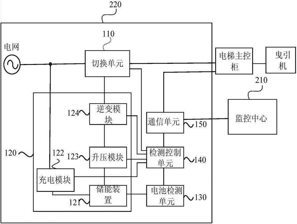
[0050] image 3 It is a schematic structural diagram of an elevator power failure emergency system provided by Embodiment 2 of the present invention. Such as image 3 As shown, the system includes a monitoring center 210 and the elevator power failure emergency device 220 described in the first embodiment.

[0051] The monitoring center 210 is used to receive the running state data and life state parameters sent by at least one elevator power failure emergency device 220, and analyze and process the obtained running state data and life state parameters. In this application scenario, the elevator power failure emergency device 220 sends running status data and life status parameters to the monitoring center 210 every preset time period. Optionally, the monitoring center 210 may actively request the running state data and life state parameters from the elevator power failure emergency device 220 .

[0052] Preferably, the monitoring center 210 is also used to obtain the curre...


PUM


Abstract

The invention discloses an elevator power failure emergency device and system. The elevator power failure emergency device comprises a switchover unit, a charging emergency unit, a battery detecting unit, a detection control unit and a communication unit, wherein an input end of the switchover unit is connected with a mains supply power grid; an output end of the switchover unit is connected withan elevator master control cabinet; the charging emergency unit is connected with the switchover unit; the battery detecting unit is connected with an energy storage device and is used for detecting the service life state parameter of the energy storage device; the detection control unit is connected with the switchover unit, the charging emergency unit and the battery detecting unit; the communication unit is connected with the detection control unit and is used for receiving the service life state parameter sent by the detection control unit; and the battery detecting unit can detect the service life state parameter of the energy storage device to improve the reliability of the elevator power failure emergency device.

Description

technical field [0001] The embodiments of the present invention relate to the technical field of elevators, in particular to an elevator power failure emergency device and system. Background technique [0002] With the continuous increase of high-rise buildings, elevators have become one of the indispensable tools in people's lives. However, due to the influence of the stability of the power system, when there is a sudden power outage, there will be an elevator trapped event, which will cause the trapped passengers to panic and even act aggressively, posing a great safety hazard. Therefore, elevator emergency devices have emerged as the times require, and power failure rescue has been listed as an essential function of elevators. [0003] The energy storage module in the elevator emergency device is a very critical part. In order to ensure the normal operation of the elevator emergency device, the detection and maintenance of the energy storage device is particularly import...

Claims


Application Information

Patent Timeline
Patent Type & Authority Applications(China)
IPC IPC(8): B66B5/00B66B5/02
CPCB66B5/0018B66B5/02
Inventor 黄诗涌黄立明王鹏钟海峰
Owner HITACHI BUILDING TECH GUANGZHOU CO LTD
Why Eureka
Try Eureka