Ground trench excavating equipment for underground pipeline burying in construction site

A technology for underground pipelines and construction sites, which is used in construction, earthmoving machines/shovels, etc., and can solve the problems of high excavation cost, time-consuming and laborious excavation process, and slow excavation speed.

Inactive Publication Date: 2017-09-08
赣州清亦华科科技有限公司
View PDF0 Cites 4 Cited by
  • Summary
  • Abstract
  • Description
  • Claims
  • Application Information

AI Technical Summary

Problems solved by technology

[0006] In order to overcome the disadvantages of slow excavation speed, time-consuming and labor-intensive excavation process, and high excavation cost when excavating underground pipelines on construction sites manually, the technical problem to be solved by the present invention is to improve the excavation speed. A kind of ground trench excavation equipment for underground pipeline burial in construction sites, fast, time-saving and labor-saving excavation process, and low excavation cost

Method used


Image

  • Ground trench excavating equipment for underground pipeline burying in construction site
  • Ground trench excavating equipment for underground pipeline burying in construction site
  • Ground trench excavating equipment for underground pipeline burying in construction site

Examples


Embodiment 1

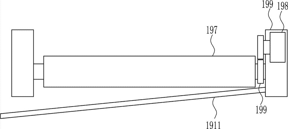
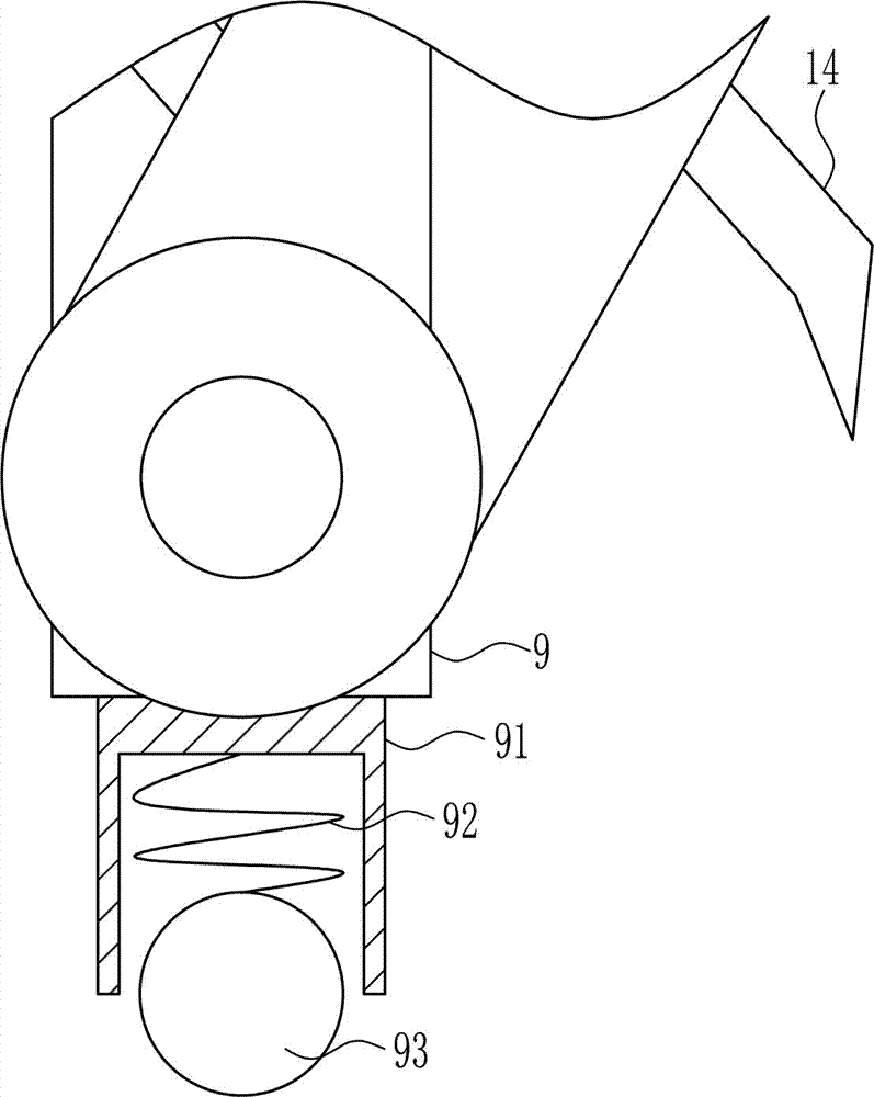
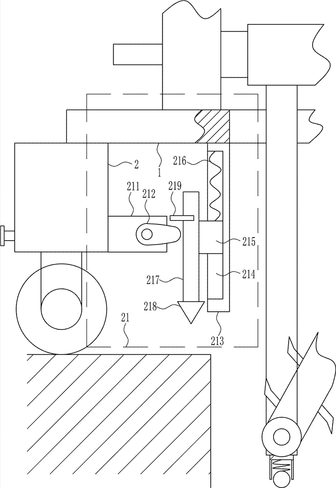
[0036] A kind of ground trench digging equipment for underground pipeline burial in construction site, such as Figure 1-8 As shown, it includes a mounting plate 1, a support block 2, a support rod 4, a tire 5, a first screw rod 7, a first pressure block 8, a first connecting rod 9, a first rotating shaft 10, a first connecting block 11, a second The shaft 12, the first runner 13, the digging knife 14, the first conveyor belt 15, the first motor 16, the second runner 17 and the first transmission strip, the left and right sides of the lower side of the mounting plate 1 are installed with supports by welding Block 2, the lower side of the support block 2 is provided with an empty slot 3, a support rod 4 is placed in the empty slot 3, the lower side of the support rod 4 is rotatably connected with a tire 5, and the outer side of the support block 2 is provided with a first threaded hole 6, the second A threaded hole 6 is internally screwed with a first screw 7, the first screw 7...

Embodiment 2

[0038] A kind of ground trench digging equipment for underground pipeline burial in construction site, such as Figure 1-8 As shown, it includes a mounting plate 1, a support block 2, a support rod 4, a tire 5, a first screw rod 7, a first pressure block 8, a first connecting rod 9, a first rotating shaft 10, a first connecting block 11, a second The shaft 12, the first runner 13, the digging knife 14, the first conveyor belt 15, the first motor 16, the second runner 17 and the first transmission strip, the left and right sides of the lower side of the mounting plate 1 are installed with supports by welding Block 2, the lower side of the support block 2 is provided with an empty slot 3, a support rod 4 is placed in the empty slot 3, the lower side of the support rod 4 is rotatably connected with a tire 5, and the outer side of the support block 2 is provided with a first threaded hole 6, the second A threaded hole 6 is internally screwed with a first screw 7, the first screw 7...

Embodiment 3

[0041] A kind of ground trench digging equipment for underground pipeline burial in construction site, such as Figure 1-8As shown, it includes a mounting plate 1, a support block 2, a support rod 4, a tire 5, a first screw rod 7, a first pressure block 8, a first connecting rod 9, a first rotating shaft 10, a first connecting block 11, a second The shaft 12, the first runner 13, the digging knife 14, the first conveyor belt 15, the first motor 16, the second runner 17 and the first transmission strip, the left and right sides of the lower side of the mounting plate 1 are installed with supports by welding Block 2, the lower side of the support block 2 is provided with an empty slot 3, a support rod 4 is placed in the empty slot 3, the lower side of the support rod 4 is rotatably connected with a tire 5, and the outer side of the support block 2 is provided with a first threaded hole 6, the second A threaded hole 6 is internally screwed with a first screw 7, the first screw 7 ...


PUM


Abstract

The invention relates to excavating equipment, in particular to ground trench excavating equipment for underground pipeline burying in a construction site and aims at achieving the technical purpose of providing the ground trench excavating equipment which is high in excavating speed, saves time and labor in the excavating process, is relatively low in excavating cost and is used for underground pipeline burying in the construction site. To achieve the technical purpose, the ground trench excavating equipment for underground pipeline burying in the construction site is provided and comprises an installation plate, supporting blocks, supporting rods, tires, a first threaded rod, a first pressing block, a first connection rod, a first rotating shaft, a first connection block, a second rotating shaft and the like. The supporting blocks are arranged on the left side and the right side of the lower side of the installation plate in a welding manner, grooves are formed in the lower side of the supporting blocks, the supporting rods are put in the grooves, and the lower sides of the supporting rods are rotationally connected with the tires. The ground trench excavating equipment achieves the effects that the excavating speed is high, time and labor are saved in the excavating process, and the excavating cost is relatively low.

Description

technical field [0001] The invention relates to an excavating device, in particular to a ground trench excavating device for laying underground pipelines at a construction site. Background technique [0002] Underground pipelines are pipelines laid underground for transporting liquids, gases or loose solids. In ancient China, underground drainage pipes made of clay have long been used. When the Ming Dynasty established its capital in Beijing, a large number of bricks and stones were used to build underground drainage pipes. It is about 1 meter wide and about 2 meters high. There are many kinds of modern underground pipelines, including circular, oval, semi-elliptical, multi-circular, oval, rectangular (single-hole, double-hole and multi-hole), horseshoe-shaped and other cross-sectional forms, using steel, cast iron, concrete, Reinforced concrete, prestressed concrete, brick, stone, asbestos cement, clay, plastic, glass fiber reinforced plastic (reinforced plastic) and oth...

Claims


Application Information

Patent Timeline
IPC IPC(8): E02F5/06
CPCE02F5/06
Inventor 不公告发明人
Owner 赣州清亦华科科技有限公司
Why Eureka
Try Eureka