Display panel driving circuit, display device and display panel driving circuit's driving method

A technology for display panels and driving circuits, applied in static indicators, instruments, etc., can solve the problems of signal deformation, small signal, affecting the charging efficiency of the panel, etc.

Inactive Publication Date: 2017-09-08
HKC CORP LTD +1
View PDF4 Cites 19 Cited by
  • Summary
  • Abstract
  • Description
  • Claims
  • Application Information

AI Technical Summary

Problems solved by technology

Therefore, the signal sent to the back end of the line is getting smaller and smaller, and the signal is seriously deformed
All ...

Method used


Image

  • Display panel driving circuit, display device and display panel driving circuit's driving method
  • Display panel driving circuit, display device and display panel driving circuit's driving method
  • Display panel driving circuit, display device and display panel driving circuit's driving method

Examples


Embodiment Construction

[0031] In order to make the purpose, technical solution and technical effect of the present invention clearer, specific embodiments of the present invention will be described below in conjunction with the accompanying drawings. It should be understood that the specific embodiments described here are only used to explain the present invention, not to limit the present invention.

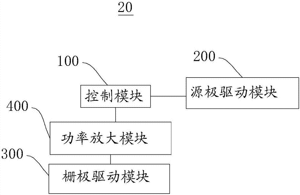
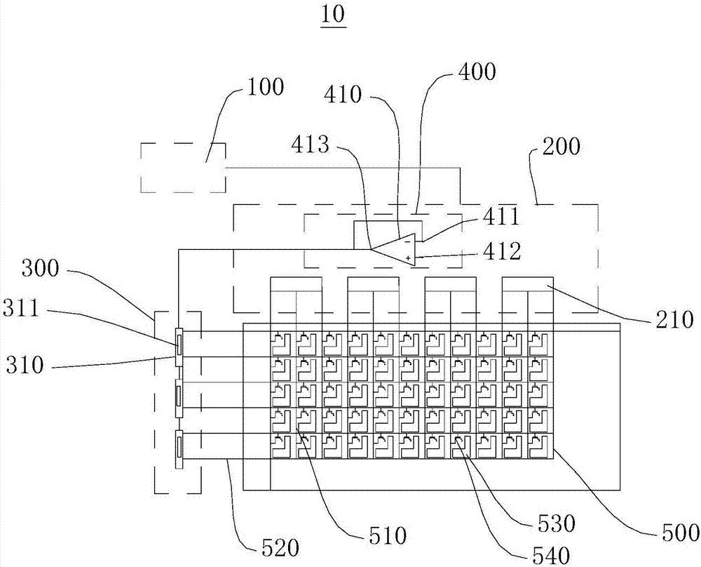
[0032] See figure 1 , the embodiment of the invention provides a display panel driving circuit 20 . The display panel driving circuit 20 includes a control module 100 and a source driving module 200 and a gate driving module 300 connected to the control module 100 . The control module 100 outputs scan signals and data signals through the gate driver module 300 and the source driver module 200 respectively. A power amplification module 400 is disposed between the control module 100 and the gate driving module 300 . The power amplifying module 400 is connected to the control module 100 and the gate d...


PUM


Abstract

The invention discloses a display panel driving circuit, a display device and a display panel driving circuit's driving method. The display panel driving circuit comprises a control module, a source electrode driving module and a gate electrode driving module in connection with the control module. The control module, through the gate electrode driving module and the source electrode driving module, outputs a scanning signal and a data signal respectively. Between the control module and the gate electrode driving module, a power amplification module is arranged. The power amplification module is connected with the control module and the gate electrode module. The scanning signal outputted from the control module is amplified by the power amplification module, and then enters the gate electrode driving module. The amplified scanning signal is capable of increasing the driving capability of the signal current on the line, and is able to quicken the responding time, reduce the signal deformation, solve the weakening problem and increase the power charging efficiency.

Description

technical field [0001] The invention relates to the display field, in particular to a display panel driving circuit, a display device and a driving method for the display panel driving circuit. Background technique [0002] When the traditional TFT-LCD (thin film transistor-liquid crystal display thin film transistor liquid crystal display) works in the gate drive circuit, the circuit itself will have a resistance effect. The thinner and longer the signal transmission line, the greater the corresponding impedance value. There will be a coupling capacitance effect between the circuit and the circuit. This creates the effect of RC delay. Both the resistance effect and the coupling capacitance effect will reduce the energy of the scanning signal and cause power loss, which will cause the RC delay effect of the circuit board. Since the scanning signal scans the pixels row by row, the voltage of the scanning signal passing through the lower pixels is lower. Therefore, the sig...

Claims


Application Information

Patent Timeline
IPC IPC(8): G09G3/36
CPCG09G3/3611
Inventor 胡水秀
Owner HKC CORP LTD
Why Eureka
Try Eureka