Expanding and supporting device and tyre mould

A technology of spreaders and support frames, applied in the field of spreaders and tire molds, can solve the problems of reducing labor intensity and high safety hazards, sliding and collapsing of supporting parts, and time-consuming safety factor, so as to reduce labor intensity and avoid The effect of scratching and ensuring stability

Inactive Publication Date: 2017-09-12
HIMILE MECHANICAL SCI & TECH (SHANDONG) CO LTD
View PDF0 Cites 0 Cited by
  • Summary
  • Abstract
  • Description
  • Claims
  • Application Information

AI Technical Summary

Problems solved by technology

[0003] However, the tooling for expansion in the workshop is relatively primitive. It is not only time-consuming and labor-intensive to use sheet metal support rods and adjustment blocks to correct and expand the coaming, but also with the increasing tightening force, the contact area at both ends is small , it is very easy to cause the support part to slip and collapse when the heavy hammer is struck, resulting in a safety accident
Moreover, this method often requires multiple strikes with a heavy hammer due to insufficient expansion force, which is not only time-consuming but also has a low safety factor.
[0004] A survey of the expanders currently on the market found that the main structural form of the expander is to drive the drive device at the axial position of the ring parts, and then drive the expansion device to expand the space. The structure has strict requirements, and the expansion force is transmitted indirectly. It is difficult to realize the expansion due to the influence of the structure when the guide ring and the surrounding plate of the tire mold are aligned; The radial position of the component is driven, but in order to ensure the uniformity of the force of the expansion, this type of expander is generally equipped with at least three driving devices evenly distributed in the ring component, and the manufacturing cost is very high
And to sum up, the two types of spreaders have a common feature, that is, the position of the expansion point where the spreader contacts the ring is relatively unchanged, and it cannot be effectively adjusted during the expansion process.
[0005] In view of the problems existing in the above-mentioned prior art, in order to solve the disadvantages of slow efficiency, reduced labor intensity and high potential safety hazards, the present invention combines years of design and use experience in related fields, supplemented by strong professional knowledge, designs and manufactures a Supporter and tire mold, to overcome the above defects

Method used


Image

  • Expanding and supporting device and tyre mould
  • Expanding and supporting device and tyre mould

Examples


Embodiment Construction

[0034] In order to facilitate the understanding of those skilled in the art, the present invention will be further described below in conjunction with the accompanying drawings.

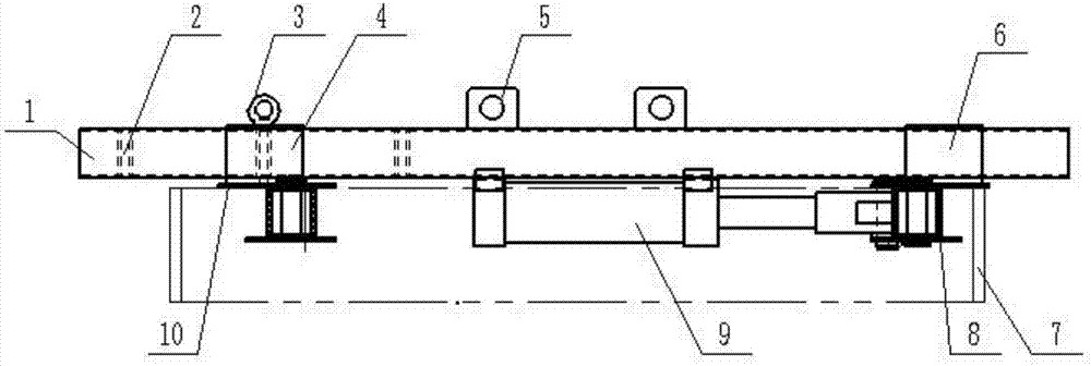
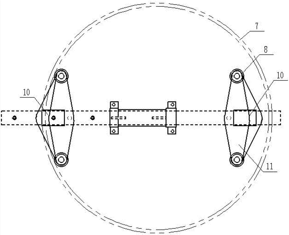
[0035] Such as figure 1 As shown, an expander includes an expansion device, and the expansion device is provided with a plurality of supporting legs 11. When expanding, the ends of the supporting legs 11 are in sliding contact with the inner wall of the ring body 7 to be expanded, so that the expansion process can be realized. The tonality contact avoids the accident of the support part slipping out and hurting people due to the constant change of the force angle when the support is expanded. In order to further ensure the stability of the sliding contact adjustment, the end of the supporting leg 11 is preferably provided with a certain radian, so that the end of the supporting leg 11 is in linear contact with the inner wall of the ring body 7 to be expanded, reducing the friction during the adjustab...


PUM


Abstract

The invention discloses a spreader, which belongs to the field of correction of ring components, and includes an expansion device, on which a plurality of supporting legs are arranged. When expanding, the ends of the supporting legs slide in contact with the inner wall of the ring to be expanded. Adjustable contact can be achieved during the expansion process, avoiding the accident of the support part slipping out and hurting people due to the constant change of the force angle during the expansion process. In order to improve processing efficiency, reduce labor intensity, and avoid axial changes of the parts to be expanded, the expansion device also includes a power mechanism and a support frame. The support legs are arranged on the support frame, and the power mechanism drives and supports the ring body to be expanded radially. The supporting legs on the frame make the supporting frame and the supporting legs only move on the plane of the ring body to be expanded.

Description

technical field [0001] The invention relates to the field of correction of ring components, in particular to a spreader and a tire mold. Background technique [0002] When assembling the ring parts, especially the guide ring and the shroud of the tire mold, it is necessary to expand the shroud and put it into the position of the outer circle of the guide ring, and then pass through the recess of the shroud and the guide ring. The air chamber is formed by welding, and it is difficult to place it without expanding the shroud. [0003] However, the tooling for expansion in the workshop is relatively primitive. It is not only time-consuming and labor-intensive to use sheet metal support rods and adjustment blocks to correct and expand the coaming, but also with the increasing tightening force, the contact area at both ends is small , when the heavy hammer strikes, it is very easy to cause the support part to slide and collapse, resulting in a safety accident. Moreover, this me...

Claims


Application Information

Patent Timeline
Patent Type & Authority Applications(China)
IPC IPC(8): B29C33/30B29C33/00
CPCB29C33/305B29C33/00
Inventor 季金强赵子水郑利黄保平范作利
Owner HIMILE MECHANICAL SCI & TECH (SHANDONG) CO LTD
Why Eureka
Try Eureka