
U-shaped two-stage differential eddy current probe, detection system and detection method

A differential eddy current and detection system technology, applied in the direction of measuring devices, analyzing materials, and material analysis by electromagnetic means, can solve differential signal errors, induction coils cannot share the same magnetic circuit, and induction coils cannot be lifted from the same height Or complete symmetry and other issues, to achieve accurate detection, suppression of lift-off effects, and easy engineering implementation

Inactive Publication Date: 2017-09-12
KUNMING UNIV OF SCI & TECH
View PDF5 Cites 8 Cited by
  • Summary
  • Abstract
  • Description
  • Claims
  • Application Information

AI Technical Summary

Problems solved by technology

[0004] The technical problem to be solved by the present invention is: the present invention provides a U-shaped two-stage differential eddy current probe, provides a detection system using the probe at the same time, and further provides a detection method of the system, the purpose is to overcome the conventional cylindrical core differential probe in the production, During processing, the lifting height of the induction coil is difficult to be completely consistent or completely symmetrical, resulting in the induction coil not sharing the same magnetic circuit, and the problem of differential signal error caused by the difference

Method used


Image

  • U-shaped two-stage differential eddy current probe, detection system and detection method
  • U-shaped two-stage differential eddy current probe, detection system and detection method
  • U-shaped two-stage differential eddy current probe, detection system and detection method

Examples


Embodiment 1

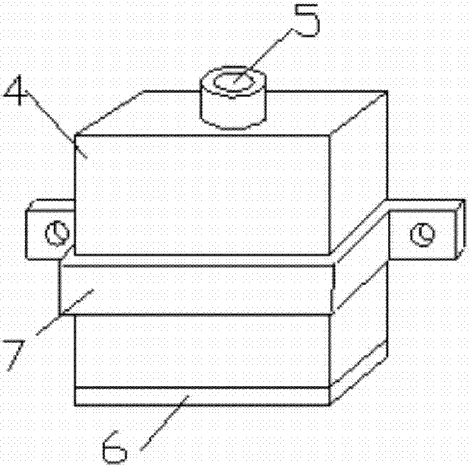
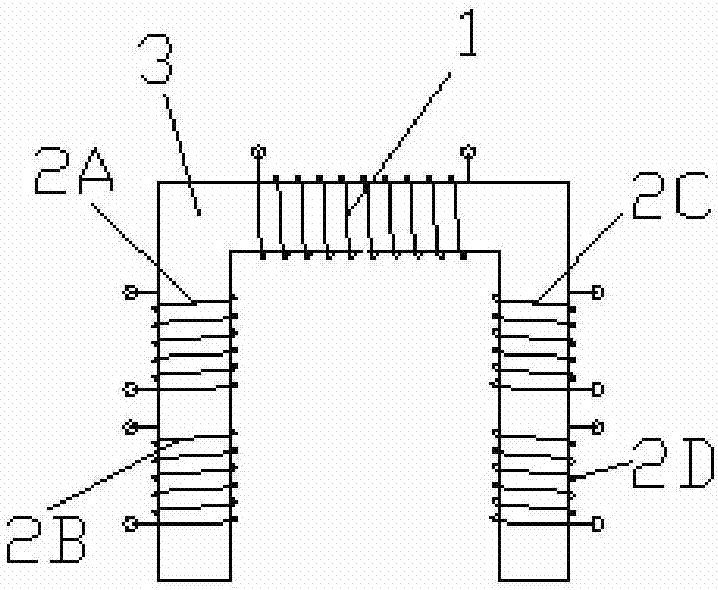
[0037] Embodiment 1: as figure 1As shown, the U-shaped two-stage differential eddy current probe includes excitation coil 1, induction coil 2A, 2B, 2C, 2D, U-shaped iron core 3, probe shell 4, terminal head 5, bottom cover 6, and fixing bracket 7; The U-shaped iron core 3 is made of silicon steel, the excitation coil 1 is wound on the top of the U-shaped iron core 3, and the four induction coils 2A, 2B, 2C, and 2D are wound on both sides of the U-shaped iron core 3, with 2 coils on each side. The four induction coils are identical and distributed axially symmetrically; the probe shell 4 is made of industrial pure iron, the top of the probe shell 4 has a hole, and the terminal 5 is fixed, and the wiring of the five coils is made by the terminal 5 The bottom cover 6 is made of ceramic fiber material, and the bottom cover 6 axially compresses and encapsulates the U-shaped iron core 3 with coils in the probe shell 4; the fixed bracket 7 is installed on the probe shell 4 On the o...


PUM

PropertyMeasurementUnit
The inside diameter ofaaaaaaaaaa
Outer diameteraaaaaaaaaa

Abstract

The invention relates to a U-shaped two-stage differential eddy current probe, a detection system and a detection method, and belongs to the technical field of nondestructive inspection. The U-shaped two-stage differential eddy current probe comprises a wiring terminal, a U-shaped iron core, an exciting coil, an induction coil and a bottom cover, wherein the eddy current detection system consists of a U-shaped differential probe, a microcontroller, a mechanical scanning device, a waveform generator, a power amplifier, a data collecting card, a serial communication module, a signal modulation module and a PC (personnel computer) host computer. The detection method comprises the following steps of performing wavelet transformation on differential signals; extracting front and back peak and trough values of the signals; calculating the front and back trough time differences; solving the crack length according to the time difference. The probe and the induction coil share an identical magnetic path; the differential signal output error due to induction coil lifting height disconformity or asymmetry of the induction coil in a conventional cylindrical iron core differential probe can be overcome; the lifting effect influence can be effectively inhibited. The detection method provided by the invention has the advantages that the engineering realization can be easily realized; the material crack defects can be fast and precisely detected.

Description

technical field [0001] The invention relates to a U-shaped two-stage differential eddy current probe, a detection system and a detection method, which are used for detecting cracks on the surface, subsurface or different depths of metals and composite materials, and belong to the technical field of non-destructive testing. Background technique [0002] Pulsed eddy current nondestructive testing is a fast and effective new nondestructive testing technology, which is mainly used for defect detection on the surface and subsurface of conductors or composite materials. Compared with other non-destructive testing techniques such as ultrasound and magnetic flux leakage, pulsed eddy current non-destructive testing has the advantages of no couplant and no magnetic saturation of the material to be tested. Pulsed eddy current non-destructive testing adopts square wave or step mode to excite the coil to generate a magnetic field and act on the material to be tested, so that an induced e...

Claims


Application Information

Patent Timeline
IPC IPC(8): G01N27/90
CPCG01N27/9006
Inventor 包俊叶波吴建德王晓东
Owner KUNMING UNIV OF SCI & TECH
Learn More