

Protection switching method and system
A technology of protection switching and partial protection, which is applied in the field of system architecture optimization of communication networks and can solve the problem of high threshold
- Summary
- Abstract
- Description
- Claims
- Application Information
AI Technical Summary
Problems solved by technology
Method used
Image

Examples
Embodiment 1
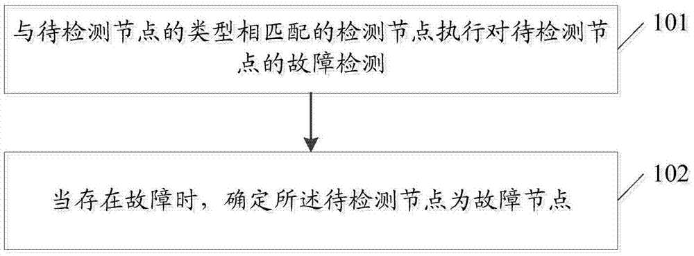
[0060] figure 2 It is a schematic flow chart of a fault detection method in an embodiment of the present invention, such as figure 2 As shown, the fault detection method of the embodiment of the present invention includes:
[0061] Step 101: The detection node matching the type of the node to be detected performs fault detection on the node to be detected;
[0062] Here, the type of the node to be detected includes network element or SFF; correspondingly, the type of the faulty node also includes network element node failure or SFF node failure.
[0063] Step 102: When there is a fault, determine that the node to be detected is a faulty node.
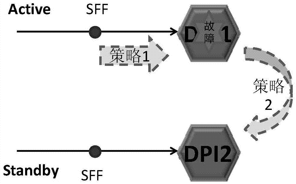
[0064] In one embodiment of the present invention, as image 3 As shown, when the type of the node to be detected is a network element, correspondingly, the detection node that matches the type of the node to be detected performs fault detection on the node to be detected including the following strategies:
[0065] Strategy 1: SF...
Embodiment 2
[0080] Figure 5 It is a schematic flowchart of a protection switching method according to an embodiment of the present invention, such as Figure 5 As shown, the protection switching method in the embodiment of the present invention includes:
[0081] Step 201: Detect whether there is a faulty node, and obtain the detection result;
[0082] Here, the fault detection process of the embodiment of the present invention may refer to the fault detection method in Embodiment 1 of the present invention.
[0083] Step 202: When the detection result is that there is a faulty node, transmit the fault information corresponding to the faulty node to the controller by sending a message through NSH;
[0084] Here, when a fault occurs at a network element node, the NSH sends the message to be sent by the SFF. At this time, the value of the Type field in the NSH message is 0; when the fault occurs at the SFF node, the NSH The sending message is sent by the standby SFF, and when Type=0, at...
Embodiment 3
[0100] Figure 8 It is a schematic diagram of the composition and structure of the detection node in the embodiment of the present invention, such as Figure 8 As shown, the detection node is a node that matches the type of the node to be detected; the detection node includes a fault detection unit 801 and a determination unit 802;
[0101] The fault detection unit 801 is configured to perform fault detection of the node to be detected;
[0102] The determining unit 802 is configured to determine that the node to be detected is a faulty node when there is a fault.
[0103] In an embodiment, the type of the node to be detected is a network element; correspondingly, when the detection node is an SFF, the fault detection unit 801 is also configured to enable physical layer detection to perform fault detection on the node to be detected detection; or, it is also used to perform fault detection on the node to be detected by sending an NSH detection message to the node to be detec...
PUM
 Abstract
Description
Claims
Application Information