Synchronous floating core pulling mechanism for large-angle oblique pulling core and guide block on cavity side of injection mold

A technology of injection mold and core-pulling mechanism, which is applied in the field of large-angle oblique core-pulling on the side of the injection mold cavity, and the field of synchronous floating core-pulling mechanism of the guide block, which can solve the problems of reducing production efficiency, increasing the volume of the mold, and increasing the tonnage of the injection molding machine, etc.

Pending Publication Date: 2017-09-15
滨海模塑集团有限公司
View PDF8 Cites 2 Cited by
  • Summary
  • Abstract
  • Description
  • Claims
  • Application Information

AI Technical Summary

Problems solved by technology

[0002] In the injection mold, if the plastic part is located on the side of the cavity and has a large-angle inclined upward chute, the existing technology usually uses an oil cylinder for oblique drawing. Since the angle of the oblique drawing is large, the inclination angle set by the oil cylinder should be consistent with the angle of the oblique drawing. Consistent

Method used


Image

  • Synchronous floating core pulling mechanism for large-angle oblique pulling core and guide block on cavity side of injection mold
  • Synchronous floating core pulling mechanism for large-angle oblique pulling core and guide block on cavity side of injection mold
  • Synchronous floating core pulling mechanism for large-angle oblique pulling core and guide block on cavity side of injection mold

Examples


Example Embodiment

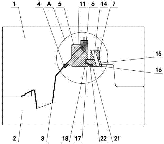
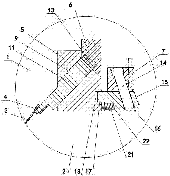
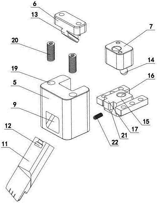
[0012] The invention relates to a large-angle oblique core-pulling on the cavity side of an injection mold, and a synchronous floating core-pulling mechanism with a guide block, such figure 1 — Figure 5 As shown, it includes a cavity 1 and a core 2. There is an injection molded plastic part 3 between the cavity and the core. The plastic part is formed with a large angle inclined upward chute 4, which is characterized in that: A guide block 5, a guide hook 6 and a guide post fixing block 7 are arranged under the cavity 1. A fixed distance slot 8 and a guide hole 9 are opened in the guide block, and a fixed distance pull nail 10 is arranged in the fixed distance groove. The nail is connected with the cavity 1, the guide hole is provided with an oblique core 11, one end of the oblique core is matched with the oblique groove 4 of the plastic part 3, and the other end of the oblique core is formed with an oblique slide groove 12 in the guide hook 6 The inclined slide rail 13 is for...


PUM


Abstract

A synchronous floating core pulling mechanism for a large-angle oblique pulling core and a guide block on the cavity side of an injection mold comprises a cavity and a core; an injection-molded plastic piece is arranged between the cavity and the core; a large-angle oblique upward chute is manufactured on the plastic piece; the mechanism is characterized in that the guide block, a guide hook and a guide column fixing block are arranged below the cavity; a fixed-distance groove and a guide hole are formed in the guide block; a fixed-distance blind rivet is arranged in the fixed-distance groove, the guide block is connected with the cavity through the fixed-distance blind rivet; the oblique pulling core is arranged in the guide hole; one end of the oblique pulling core is matched with the chute of the plastic piece, and the other end of the oblique pulling core is provided with an oblique chute; an oblique sliding rail is arranged under the guide hook, and the oblique sliding rail is matched with an oblique sliding groove; an oblique guide column is arranged in the guide column fixing block; a sliding block is arranged on the core; an oblique guide hole is formed in the sliding block and is matched with the oblique guide column; a pressing block is manufactured on one side of the sliding block; a limiting groove is formed in the side wall of the guide block; and the pressing block makes contact with the limiting groove.

Description

technical field [0001] The invention relates to an injection mold, in particular to a large-angle oblique core-pulling mechanism on the cavity side of the injection mold and a synchronous floating core-pulling mechanism of a guide block. Background technique [0002] In the injection mold, if the plastic part is located on the side of the cavity and has a large-angle inclined upward chute, the existing technology usually uses an oil cylinder for oblique drawing. Since the angle of the oblique drawing is large, the inclination angle set by the oil cylinder should be consistent with the angle of the oblique drawing. Consistent, so the height of the mold needs to be made higher to meet the oblique pumping of the oil cylinder, resulting in an increase in the volume of the mold, increasing the tonnage of the injection molding machine, and increasing the development cost of the mold. The mold can only be opened when the core is pulled by the oil cylinder, thereby reducing the prod...

Claims


Application Information

Patent Timeline
IPC IPC(8): B29C45/33
CPCB29C45/33B29C45/332B29C2045/338
Inventor 赖小强牟能杰
Owner 滨海模塑集团有限公司
Why Eureka
Try Eureka