Fiber grating hydrophone and sound pressure sensing system

A fiber grating and hydrophone technology, applied in instruments, measuring ultrasonic/sonic/infrasonic waves, measuring devices, etc., can solve the problems of bulky, vulnerable to damage, limited working water depth, etc., to improve hydrostatic pressure resistance, The effect of balanced hydrostatic pressure and simple structure

Active Publication Date: 2017-09-15
LASER RES INST OF SHANDONG ACAD OF SCI
View PDF4 Cites 5 Cited by
  • Summary
  • Abstract
  • Description
  • Claims
  • Application Information

AI Technical Summary

Problems solved by technology

This kind of hydrophone has a complex structure and a bulky volume, which is not conducive to the miniaturization of the hydrophone structure, and is easily damaged, and the working water depth is limited

Method used


Image

  • Fiber grating hydrophone and sound pressure sensing system
  • Fiber grating hydrophone and sound pressure sensing system
  • Fiber grating hydrophone and sound pressure sensing system

Examples


no. 1 example

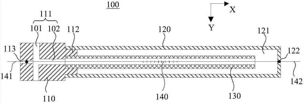
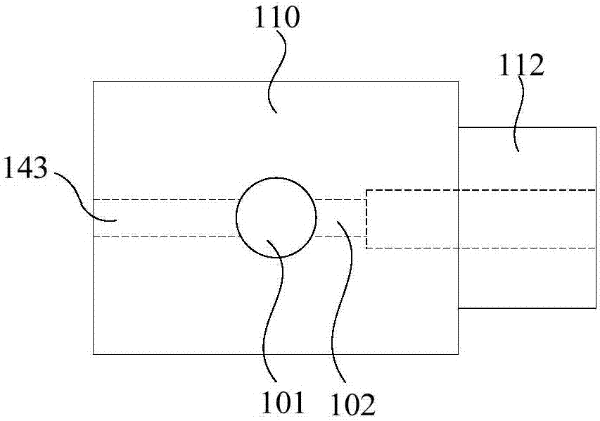
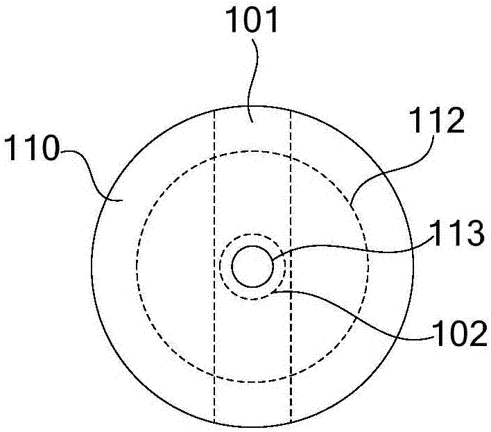
[0034] Such as figure 1 As shown, the first embodiment of the present invention provides a fiber grating hydrophone 100 , including a base 110 , an acoustic tube 120 , a balance tube 130 and a fiber grating 140 . The first end of the acoustic tube 120 is connected to the base 110 to form a cavity 121 . Both the balance tube 130 and the fiber grating 140 are disposed in the cavity 121 of the acoustic tube 120 . The base 110 is provided with a communication hole 111 for introducing external fluid into the cavity 121 . The first opening of the balance tube 130 communicates with the communication hole 111 , and the second opening of the balance tube 130 communicates with the cavity 121 , so that after the external fluid enters through the communication hole 111 , it flows into the cavity 121 through the balance tube 130 .

[0035]It should be noted that the sound-sensitive tube 120 and the base 110 may be integrally formed, or may be two independent components. In this embodime...

no. 2 example

[0059] Such as Image 6 As shown, the second embodiment of the present invention also provides a sound pressure sensing system 10, including a light source device 200, a demodulation device 300, and the fiber Bragg grating hydrophone 100 provided in the above-mentioned first embodiment. Wherein, there may be one fiber grating hydrophone 100, or there may be several. Such as Image 6 As shown, both the light source device 200 and the demodulation device 300 are optically coupled to the fiber Bragg grating 140 of the fiber Bragg grating hydrophone 100 , where the arrows are used to indicate optical signals. The detection light emitted by the light source device 200 enters the fiber grating 140, and the detection light reflected by the fiber grating 140 enters the demodulation device 300 as signal light carrying the sound pressure signal to be measured, and is demodulated by the demodulation device 300 to obtain the sound pressure to be measured.

[0060] In this embodiment, th...


PUM


Abstract

The invention provides a fiber grating hydrophone and a sound pressure sensing system, and belongs to the technical field of fiber sensors. The fiber grating hydrophone comprises a substrate, a sound sensitive cylinder, a balancing pipe and a fiber grating. A communication hole is arranged in the substrate. The first end of the sound sensitive cylinder is connected with the substrate, thereby forming a cavity body. The balancing pipe is arranged in the cavity body. The first opening of the balancing pipe communicates with the communication hole. The second opening of the balancing pipe communicates with the cavity body. The fiber grating is arranged in the cavity body and used for measuring axial deformation of the sound sensitive cylinder under the functions of to-be-measured sound pressure signals and outputting signal light carrying the to-be-measured sound pressure signals. According to the invention, the fiber grating hydrophone is small in size, and simple in structure; miniaturization of the fiber grating hydrophone is facilitated; static water pressure is effectively balanced; static water pressure resisting ability is improved; and the frequency measurement range of the sound pressure signals is enlarged.

Description

technical field [0001] The invention relates to the technical field of optical fiber sensors, in particular to an optical fiber grating hydrophone and a sound pressure sensing system. Background technique [0002] Compared with conventional electromagnetic sensors, optical fiber sensors have obvious advantages in terms of sensitivity, large dynamic range, reliability, and multiplexing capabilities, and have become an important direction for the development of high-performance sensors. Optical fiber hydrophone is an instrument that detects sound in water by using the light transmission characteristics of optical fiber and the modulation effect generated by the sound pressure of the surrounding environment. Compared with traditional electromagnetic hydrophones, optical fiber hydrophones have the following advantages: high sound pressure sensitivity, no electromagnetic interference, small size, waterproof and corrosion resistance, and both sensing and transmission. It has good...

Claims


Application Information

Patent Timeline
Patent Type & Authority Applications(China)
IPC IPC(8): G01H9/00
CPCG01H9/004
Inventor 张发祥张晓磊姜邵栋李明任庆洋倪家升王昌
Owner LASER RES INST OF SHANDONG ACAD OF SCI
Why Eureka
Try Eureka