
Programmable logic control device and high-speed signal receiving method

A programming logic control and high-speed signal technology, applied in the field of communication, can solve the problems of poor adaptability and achieve the effect of strong adaptability

Active Publication Date: 2017-09-15
深圳市恒扬数据股份有限公司
View PDF5 Cites 9 Cited by
  • Summary
  • Abstract
  • Description
  • Claims
  • Application Information

AI Technical Summary

Problems solved by technology

[0004] The purpose of the present invention is to provide a programmable logic control device and its high-speed signal receiving method, aiming at solving the problems existing when the existing programmable logic control device adopts the traditional phase alignment adjustment technology to adjust the phase of the high-speed signal connected. The problem of poor adaptability

Method used


Image

  • Programmable logic control device and high-speed signal receiving method
  • Programmable logic control device and high-speed signal receiving method
  • Programmable logic control device and high-speed signal receiving method

Examples


Embodiment Construction

[0017] In order to make the object, technical solution and advantages of the present invention clearer, the present invention will be further described in detail below in conjunction with the accompanying drawings and embodiments. It should be understood that the specific embodiments described here are only used to explain the present invention, not to limit the present invention.

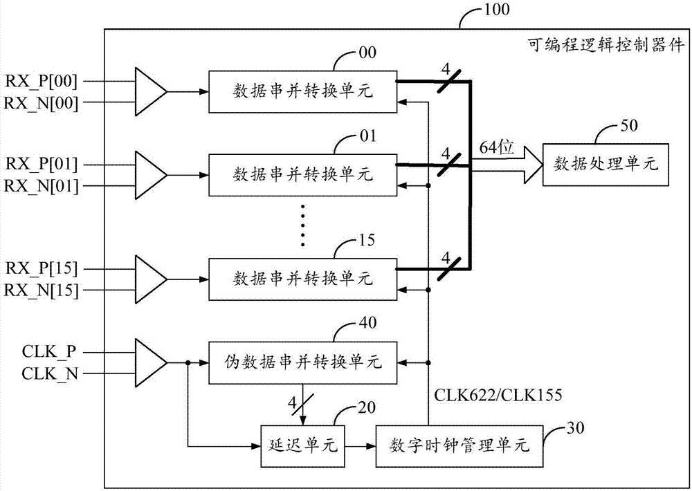
[0018] see figure 1 , is a structural block diagram of a programmable logic control device provided by an embodiment of the present invention. For ease of description, only the parts related to the embodiments of the present invention are shown, and the details are as follows:

[0019] A programmable logic control device 100, which receives high-speed signals through a parallel interface (not shown in the figure). Wherein, the bit width of the parallel interface can be set according to actual requirements, and there is no limitation here. In the embodiment of the present invention, the programma...


PUM


Abstract

The present invention discloses a programmable logic control device and a high-speed signal receiving method thereof. The programmable logic control device which includes a data series-parallel conversion unit, a delay unit, a digital clock management unit and a pseudo-data series-parallel conversion unit is adopted; the pseudo data series-parallel conversion unit performs series-parallel conversion on receive second clock signals so as to obtain pseudo-data signals; and since the path of the second clock signals and the path of data signals in the programmable logic control device are totally the same, the phases of the second clock signals, pseudo-data signals and data signals are totally consistent with one another, and therefore, when the delay unit samples the pseudo-data signals according to received first clock signals, the sampling points of the data signals can be searched out according to sampling results, the sampling edge of the first clock signals is adjusted to the number of the sampling points of the data signals, so that high-speed signal receiving can be completed. According to the programmable logic control device and the high-speed signal receiving method thereof of the invention, phase alignment adjustment of the high-speed signals can be completed without a hardware simulation circuit required, and therefore, the method has high adaptability.

Description

technical field [0001] The invention relates to the field of communication technology, in particular to a programmable logic control device and a high-speed signal receiving method thereof. Background technique [0002] In large-scale local area networks or Gigabit or 10 Gigabit Ethernet of operators, the access problem of high-speed signals is a key problem that must be faced and solved in high-performance processing. In the prior art, the processing capability of the device is generally adapted to the processing capability of the device by parallelizing and reducing the speed of the serial signal. Typically, a signal with a rate of up to 10GHz is generally connected to an FPGA (Field Programmable Gate Array, programmable logic control device) through a 16-bit wide 622MHz LVDS (Low-Voltage Differential Signaling, low-voltage differential signal). The rate is as high as 622MHz, so that the effective time window occupied by each bit signal is only 1.6ns (nanosecond), which m...

Claims


Application Information

Patent Timeline
Patent Type & Authority Applications(China)
IPC IPC(8): G05B19/05
Inventor 魏星平
Owner 深圳市恒扬数据股份有限公司
Learn More